Get in Touch with BBP

Electrostatic Motor: Working Principle and Pump Drive Prospects

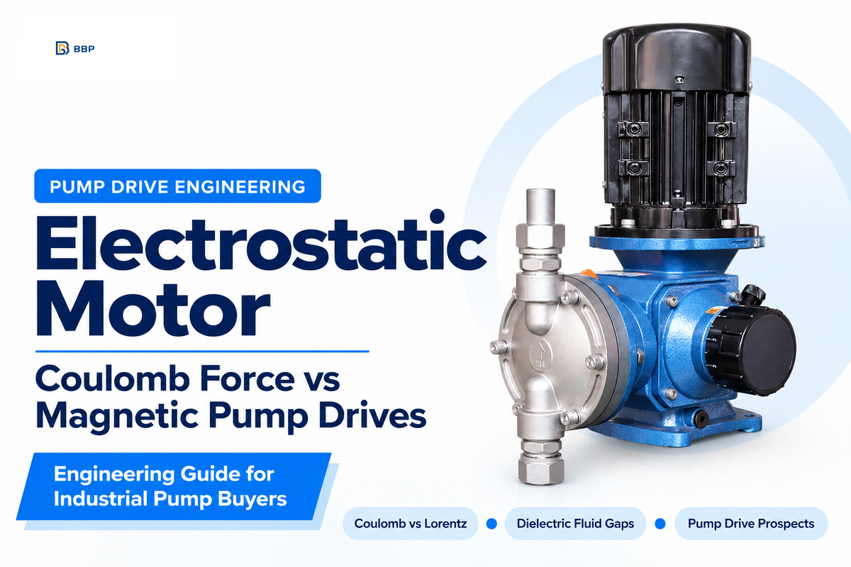
An electrostatic motor is an electric motor that produces rotation or linear motion by means of electrostatic charge attraction across electrode plates. An electromagnetic motor uses an electric current through copper windings to build a magnetic field. An electrostatic machine uses high voltage across a narrow, insulated gap in a capacitor. In specifications for its ZeroMag product, C-Motive reports that its liquid-dielectric motors reduce copper usage by 90% and eliminate rare-earth permanent magnets. C-Motive indicates low-speed direct drives for 1 to 4 HP (0.75 to 3.0 kW) duties and below 400 RPM.
Engineering Scope & Key Takeaways:
- Physics Boundary: Atmospheric air has an approximate breakdown field of 3 kV/mm, influenced by gap size and electrode geometry; at a fixed total electric-field magnitude E, the maximum Maxwell shear stress is εE²/2. At an achievable 1.5 T flux density in iron, the cited magnetic stress scale (B²/μ₀) is 1.79 MPa (260 psi), or ½B²/μ₀ = 0.895 MPa tangential limit. Flooding a 0.8 mm gap with aprotic dielectric fluid raises measured electrostatic shear stress to 13.8 kPa (2 psi).
- Under a July 8, 2026 agreement, Richardson Electronics provides design-for-manufacturing, Alpha and Beta pilot production, and volume manufacturing services for C-Motive’s ZeroMag drive controller, preparing for commercial controller production beginning in calendar 2027.
- During laboratory testing, a 360 W, 18 Nm, 200 RPM (approximately 377 W calculated shaft output) electrostatic prototype drove a low-speed hydraulic positive-displacement pump. Higher-speed or higher-power centrifugal, axial-flow, and slurry pumps use electromagnetic AC motors classified under IEC 60034-30-1 or IEC TS 60034-30-2:2016.
- BBP Manufacturing Co. Ltd produces various types of industrial pumps (centrifugal, slurry, axial flow and submersible) using standard IEC and NEMA electromagnetic motors. BBP does not design, manufacture, or sell electrostatic motors.
What Is an Electrostatic Motor and How Does Coulomb Force Replace Magnetism?
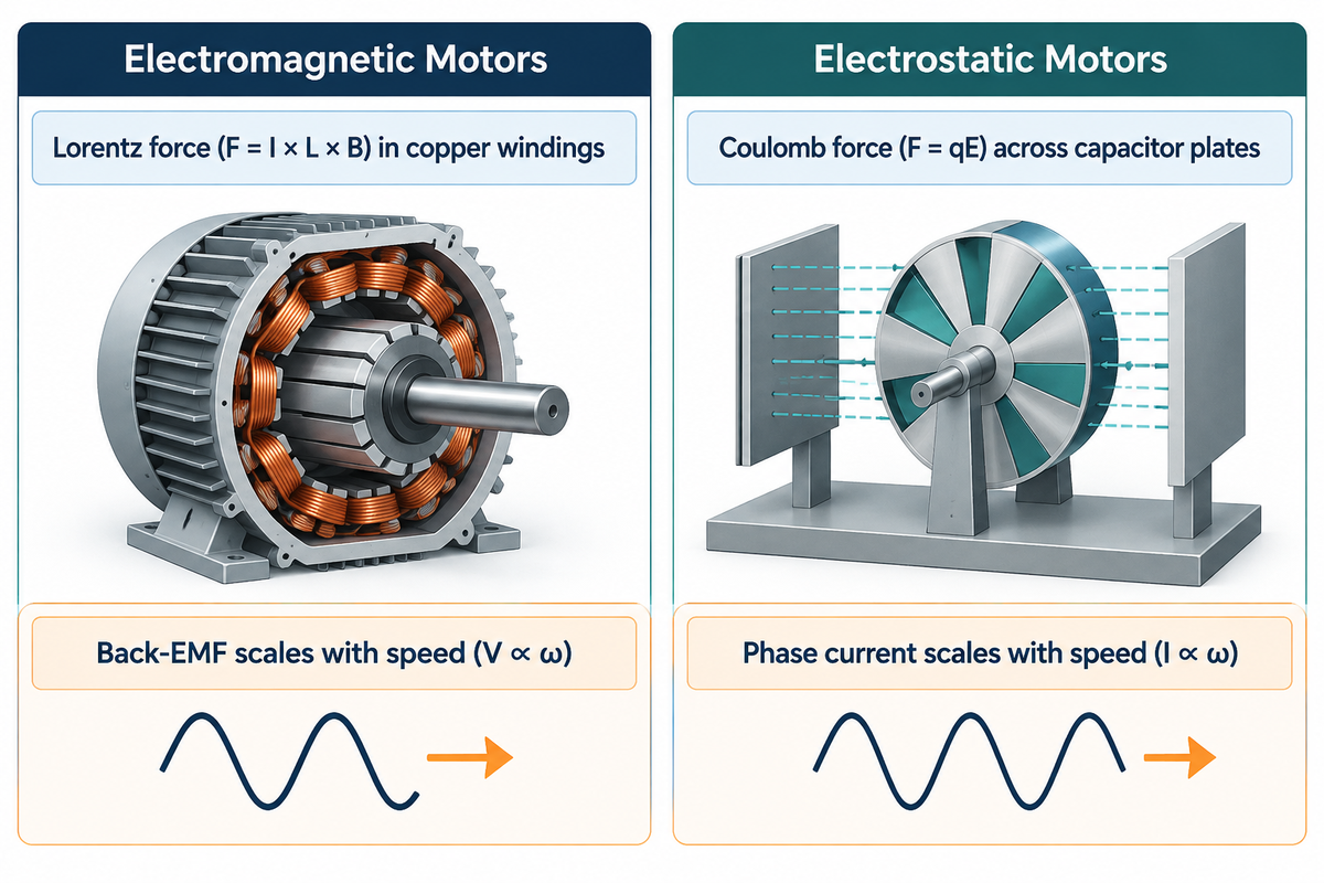
An electrostatic motor exploits Coulomb force (F = qE) between charged stators and rotor electrodes to convert electrical power into shaft torque. Standard industrial magnetic motors use Lorentz force (F = I × L × B) instead. The copper windings and laminated electrical steel cores in conventional electromagnetic motors produce and guide magnetic flux. Rotary electrostatic motors replace magnetic flux with an electric field between thin circuit-board or aluminum plates. This capacitive structure eliminates rare earth permanent magnets and large stator coils.
Historically, electrostatics was nearly 80 years older than electromagnetism. Andrew Gordon and Benjamin Franklin built the first rotary electrostatic wheels in the 1740s. Michael Faraday demonstrated the magnetic homopolar motor 73 years later in 1821. The devices of the 1740s functioned like an inverted electrostatic generator. They used static electricity and charge repulsion in open air to turn very light rotating assemblies.
How Does Electric-Magnetic Duality Reverse Voltage and Current Roles?
Electric-magnetic duality swaps the mechanical roles of voltage and current across the motor gap. At fixed geometry and torque angle, the synchronous torque component of a separately excited electrostatic motor is proportional to the product of the stator and rotor voltages. Electromagnetic torque is proportional to torque-producing current when magnetic flux is kept constant. Examples from Professor Daniel Ludois’s lab at UW-Madison WEMPEC, coupled with discussions on Electrical Engineering StackExchange demonstrate this duality. In an electromagnetic motor, back-EMF voltage is proportional to rotational speed (V ∝ ω). In an electrostatic machine, phase current is proportional to rotational speed (I ∝ ω).
This reversal changes how motors behave during low-speed operation and zero-speed holds. Conventional induction motors and permanent-magnet servo motors need to push continuous current through copper windings to hold a stalled load. This current generates I²R Joule heat and can cause the winding insulation to overheat. When an electrostatic motor holds a stalled load, no charges commute across the plates and phase current drops to milliamps of leakage current.
| Engineering Parameter | Electromagnetic Motors (Induction, PMSM, Synchronous Reluctance) | Air-Gap Electrostatic Motors (Corona & MEMS Actuators) | Liquid-Dielectric Electrostatic Motors (Macro-Scale Capacitive SEM) |
|---|---|---|---|
| Governing Force Law | Lorentz magnetic force (F = I × L × B) | Coulomb charge attraction / air-gap Maxwell stress | Capacitive Maxwell shear stress in dielectric fluid |
| Primary Torque Relationship | Torque current at constant magnetic flux (T ∝ Φ × I) | Single-gap electrode voltage squared at fixed dC/dθ (T ∝ V²) | Stator-rotor voltage product (T ∝ Vs × Vr × cos γ) plus elastance |
| Speed Driver | Applied voltage & electrical frequency (V ∝ ω) | Ion transfer or switching pulse rate | Charging current & electrical frequency (I ∝ ω, ~100 poles) |
| Active Structural Materials | Electrical steel laminations, copper windings, rotor bars or magnets | Insulated rotor wheel or etched silicon wafer | Fiberglass PCB or stamped aluminum plates, dielectric liquid |
| Zero-Speed Stall Hold Loss | Continuous I²R copper winding heat | Corona ionization and air leakage loss | Extremely low: Control Engineering reports C-Motive ZeroMag zero-speed holding power below 0.2% of full power |
How Does a Liquid-Dielectric Electrostatic Motor Generate Continuous Torque Without Copper Windings?
A liquid-dielectric electrostatic motor generates continuous torque by switching multi-phase kilovolt AC waveforms across interleaved stator and rotor capacitor disks in an insulating fluid. Unlike induction motors, which use electromagnets to pull iron teeth, this drive uses charges on conductive traces on stationary and rotating plates to attract the negatively charged and positively charged rotor electrodes to the advancing stator electric field.
How Do Interleaved Stator and Rotor Electrode Plates Create Variable Capacitance Torque?
At a fixed voltage, electrostatic torque is given by T = ½ × V² × dC/dθ. A separately excited three-phase motor also yields torque via capacitive coupling between its stator and rotor voltages. Each disc has radial electrode teeth made of copper or aluminum that are electrically insulated by a thin coating. Applying a kilovolt potential across the 0.8 mm gap stores electrostatic co-energy between the opposing teeth.
This relationship is derived by Ludois et al. in IEEE JESTPE (Volume 10, Issue 1, 2022). For the variable-capacitance model described there, torque follows the co-energy derivative:
T(θ) = ½ × Vs² × dC(θ)/dθ
In a separately excited synchronous electrostatic machine (SEM), direct-current voltage Vr excites the rotor while three-phase alternating-current voltage Vs excites the stator across P poles. The total torque along the shaft is the sum of synchronous reaction torque and salient elastance torque:
T = (3P / 4) × [ 2 × Cm × Vs × Vr × cos γ + (Cd − Cq) × Vs² × sin(2γ) ]
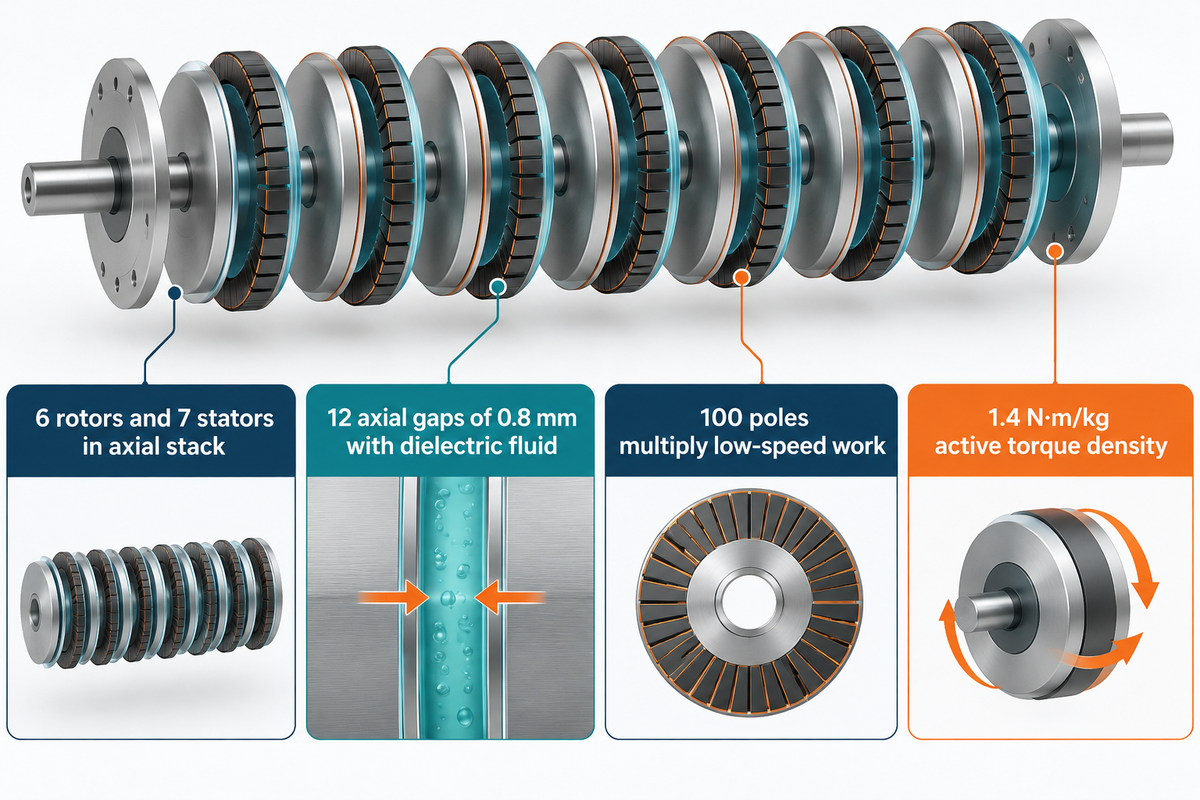
Fine radial tooth spacing gives a single disc pair roughly 100 poles. That high pole count multiplies mechanical work per revolution at low speeds without a mechanical gearbox.
Why Do Macroscale Electrostatic Motors Stack Thin PCB Plates Instead of Iron Cores?
High-density active-material packing in a compact axial stack is a key feature of thin printed circuit board (PCB) electrodes. The liquid-filled prototype reported by Ge, Ghule, and Ludois achieved an active-material torque density of 1.4 N·m/kg with 12 axial gaps of 0.8 mm. In conventional magnetic motors, strong magnetic fields flow through thick electrical steel teeth. In an electrostatic motor, torque depends on facing surface area, strength of the electric field, gap thickness, permittivity of the fluid, and tooth geometry.
According to USPTO Patent US10958191B2, engineers multiply the active shear area by cascading multiple thin discs along the shaft. The benchmark liquid-filled prototype built by Ge, Ghule, and Ludois stacks 6 rotors and 7 stators separated by 12 axial gaps of 0.8 mm. Lightweight fiberglass PCB discs, in lieu of heavy iron cores, yield 1.4 N·m/kg active torque density (0.76 N·m/kg total mass).
How Does Electronic Commutation Maintain Rotation and Eliminate Stalled Holding Heat?
Electronic commutation steps multi-phase kilovolt AC potentials across stationary electrode teeth via a current-source inverter (CSI). As reported in Control Engineering, C-Motive ZeroMag zero-speed holding power is less than 0.2% of full power. An optical encoder or an internal capacitance-sensing method determines rotor position during commutation. Once the rotor stops at the target angle, the drive locks the static voltage vector across the plates. The locked machine draws far less energy than a magnetic servo motor.
What Are the Main Types of Electrostatic Motors Across Micro and Macro Scales?
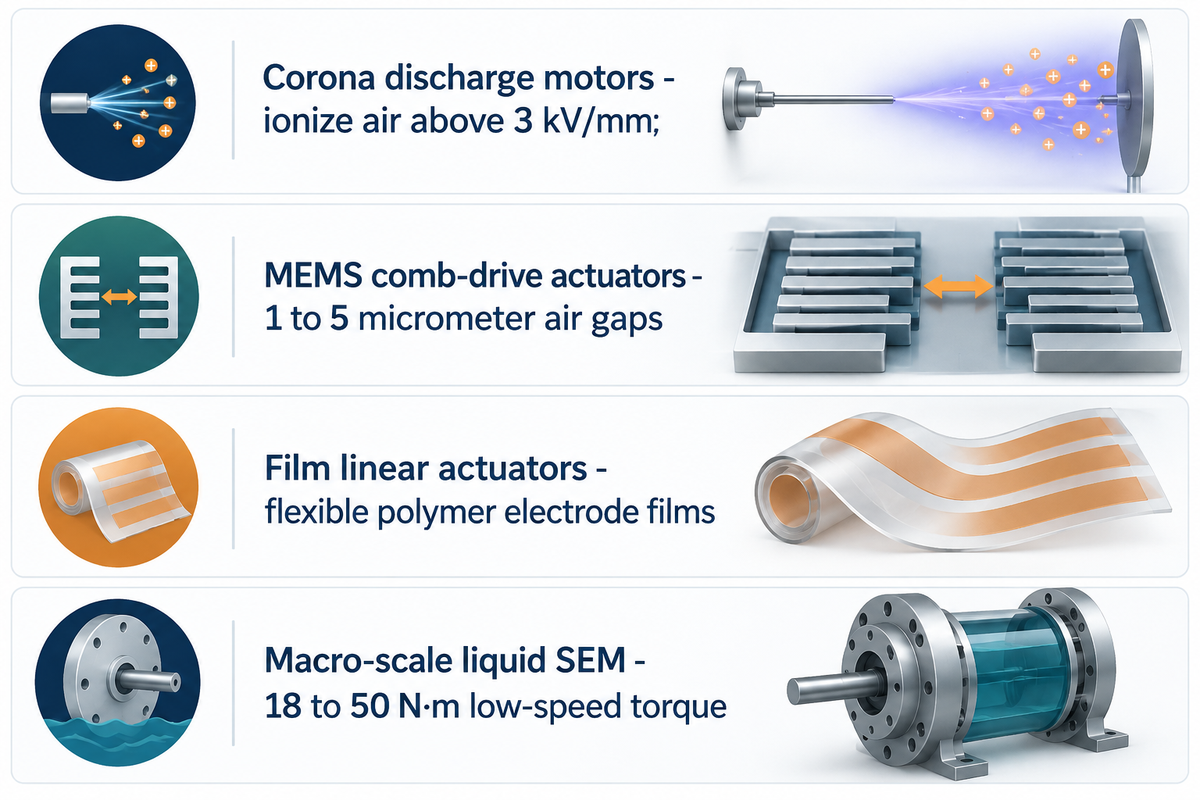
Electrostatic motors can be divided into Category I open-air charge-conduction units and Category II machines that employ insulated electrodes and capacitance across micro and macro scales. Across laboratory and industrial motor designs, four major architectures can be discerned.
- Category I Corona discharge motors (Franklin wheels from the 1740s and classroom demonstrations) use sharp needle electrodes to ionize air above 3 kV/mm. A display at the Hamilton Museum of Steam & Technology demonstrates this principle. Corona motors also transfer charge through localized air ionization. Leakage of charge causes losses, while spark breakdown can interrupt operation.
- Category II MEMS comb-drive actuators use silicon wafer fabrication to etch micro-rotors and cantilever beams in 1 to 5 micrometer air gaps. Paschen’s law holds true at these micrometer distances, suppressing spark breakdown. MEMS comb-drive actuators use electrostatic forces to produce linear displacement or limited angle rotation in optical switches and sensors at 30 to 100 volt levels. Continuous-rotation micromotors use different mechanical layouts.
- Category II film type linear electrostatic actuators make use of flexible polymer films with fine electrodes which move radially or linearly across a thin liquid film.
- Category II macro-scale, liquid dielectric synchronous electrostatic motors (SEM) employ PCB or aluminum discs submerged in dielectric fluid at 2.5 to 5 kV-rms. These devices can generate 18 to 50 N·m of low-speed torque in bench and pilot units.
Why Do Corona Motors Fail to Scale Above Tens of Watts?
Corona motors fail to scale above tens of watts because atmospheric air ionizes around 3 kV/mm, capping the cited electrostatic stress scale (ε₀E²) at 79.65 Pa (0.012 psi) and the tangential shear limit (½ε₀E²) at 39.84 Pa. As documented in Ludois et al. (IEEE JESTPE, 2022), continuous corona conduction wastes most input power as air ionization heat, ozone, and acoustic noise. Typical corona demonstration efficiency remains near 15%.
Why Are Air-Gap Electrostatic Motors Weak at High RPM and How Do Dielectric Fluids Solve Breakdown?
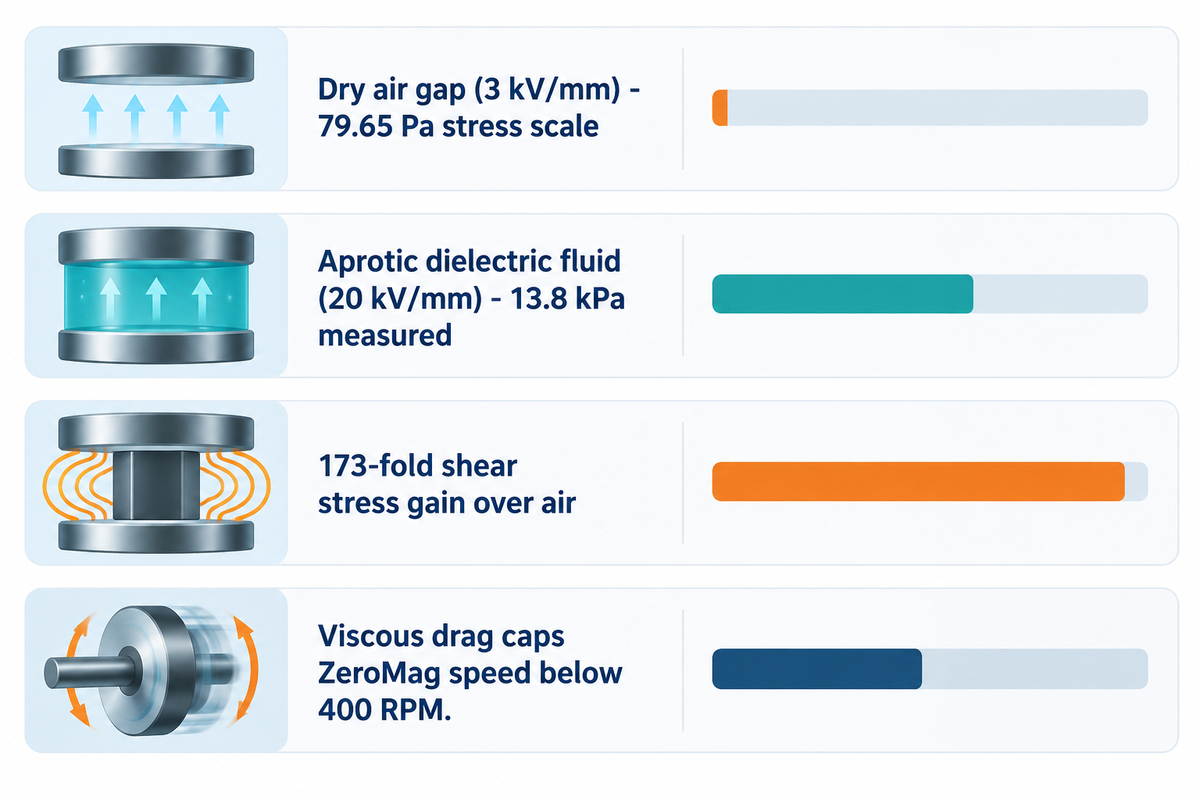
Air-gap electrostatic motors are weak at macro scale because vacuum permittivity (ε₀ = 8.854 × 10⁻¹² F/m) and ~3 kV/mm air breakdown limit the electrostatic stress scale (ε₀E²) to 79.65 Pa (or ½ε₀E² = 39.84 Pa tangential shear stress). At a magnetic field of 1.5 T in iron, the cited magnetic stress scale (B²/μ₀) reaches 1.79 MPa (260 psi), or ½B²/μ₀ = 0.895 MPa, which represents the limit of shear stress. Ludois et al. report dielectric-liquid shear stress of 13.8 kPa, while C-Motive specifies ZeroMag motors for operation below 400 RPM as liquid-gap viscous losses increase with speed.
Why Is Air-Gap Electrostatic Shear Stress Four Orders of Magnitude Lower Than Magnetic Shear Stress?
Using the shear-stress equation below, with εr = 1 and E = 3 MV/m, gives a maximum air-gap shear-stress of approximately 39.8 Pa. All stress comparisons must be made using the same definition. These field-based limits don’t represent continuous motor output. As confirmed by Wiley Advanced Intelligent Systems, electrostatic Maxwell shear stress τes scales linearly with relative permittivity εr and quadratically with electric field E.
τes = ½ × ε₀ × εr × E² × sin(2θ)
Dry air has a relative permittivity of εr = 1.0 and breaks down near 3 kV/mm. Filling the 0.8 mm gap with an aprotic dielectric fluid (εr = 3.8 to 7.4 in Gen-1 fluids, or εr ≈ 20 in Gen-2 fluids) raises breakdown strength to 20 kV/mm. Measured Maxwell shear stress in Ludois et al. (2022) reaches 13.8 kPa (2 psi). That represents a 173-fold gain over the 79.65 Pa air stress scale.
| Gap Medium & Topology | Material Constant (μ₀ in H/m or Dimensionless εr) | Field Ceiling (Bmax or Emax) | Maxwell Shear Stress Limit | Reported Torque Density & Operating Scope |
|---|---|---|---|---|
| Magnetic Air Gap in Electrical Steel | μ₀ = 4π × 10⁻⁷ H/m (absolute permeability) | 1.5 T achievable iron flux density | 1.79 MPa (260 psi) B²/μ₀ scale (0.895 MPa ½B²/μ₀); 20–100 kPa continuous motor air gap | 2.0–15+ N·m/kg; IE3–IE5 efficiency classes (IEC 60034-30-1) |
| Atmospheric Air Electrostatic Gap | εr = 1.0 (ε₀ = 8.854 × 10⁻¹² F/m) | 3 kV/mm (3 MV/m air breakdown) | 79.65 Pa (0.012 psi) ε₀E² scale (39.84 Pa ½ε₀E²) | <0.01 N·m/kg; ~15% corona demo (Ludois et al., 2022) |
| Gen-1 Liquid Dielectric Gap (0.8 mm) | εr = 3.8–7.4 (aprotic fluid, σ ≤ 10⁻¹⁰ S/m) | 20 kV/mm (5 kV-rms stator) | 13.8 kPa (2.0 psi) measured (Ludois et al., 2022) | 1.4 N·m/kg active (0.76 N·m/kg total); C-Motive ZeroMag rated <400 RPM |
| Gen-2 High-Permittivity Liquid Gap | εr ≈ 20 (proprietary aprotic blend) | Halved stator voltage (~2.5–3 kV class) | 13.8–20+ kPa with commercial 4.5 kV IGBTs | 18 N·m / 360 W at 200 RPM bench demonstrator (~377 W calculated shaft output) |
Why Do Viscous Fluid Drag and Capacitive Charging Current Limit Liquid-Dielectric Motors Above 400 RPM?
C-Motive specifies ZeroMag motors for operation below 400 RPM. Spinning rotor discs through a narrow liquid gap at higher speeds increases Couette viscous drag torque (∝ ω) and viscous power loss (∝ ω²) as well as 100-pole capacitive charging current (I = ωCV). High relative permittivity isn’t sufficient for the fluid. Pure water has εr > 80, but autoionization results in a conductivity of σ ≈ 5.5 × 10⁻⁶ S/m. In the liquid-gap machines covered in the research review, aprotic dielectric fluids with conductivity at or below 10⁻¹⁰ S/m, reduce leakage current and resistive heating.
How Does Dielectric Fluid Viscosity Cap Rotational Speed Below 400 RPM?
P_viscous ∝ (μ × ω² × R⁴) / h
In 1965, R A Vanslette tested a silicone-nitrile liquid electrostatic motor that multiplied electric displacement 20-fold. However, fluid viscosity prevented the rotor from achieving its synchronous speed of 1,500 RPM. According to engineers on Hacker News, low-viscosity fluids (0.67 to 5 cP) and kilovolt switching losses make low-speed direct drives preferable.
Which Companies Build Macro-Scale Electrostatic Motors and How Do Magnet-Free Pump Motor Alternatives Compare?
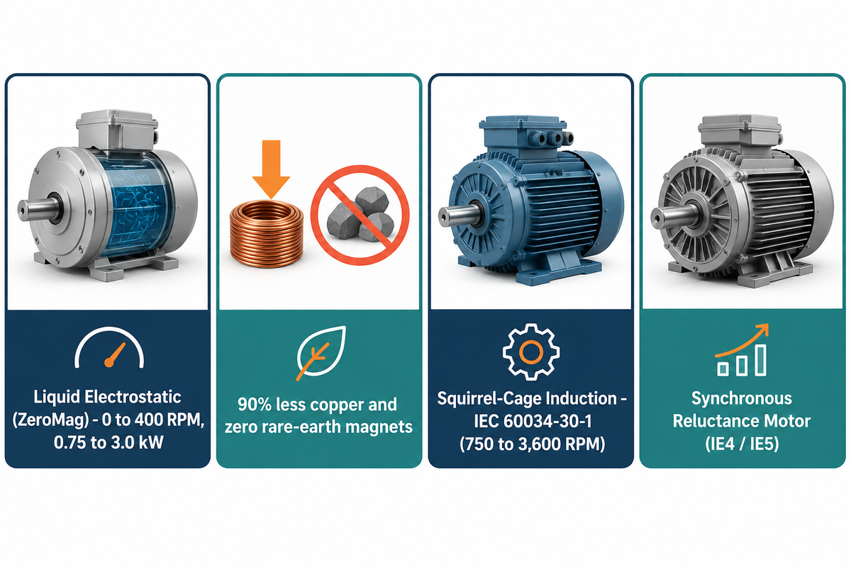
C-Motive Technologies, a spinout from UW–Madison’s WEMPEC, manufactures macro-scale liquid-dielectric electrostatic motors. Commercially available synchronous reluctance and squirrel-cage induction motors (IEC 60034-30-1 and IEC TS 60034-30-2:2016) serve permanent-magnet-free pump duties. Professor Daniel Ludois’s lab at UW, Madison develops axial-gap synchronous electrostatic machines.
- C-Motive Technologies (Middleton and Madison, WI, USA) commercializes ZeroMag, a liquid-dielectric motor platform (1 to 4 HP, under 400 RPM) based on UW, Madison WEMPEC patents.
- Axial-gap synchronous electrostatic machines, developed by Professor Daniel Ludois’s lab at UW, Madison, have been tested, and a 360 W, 18 N·m, 200 RPM hydraulic positive-displacement pump bench drive has been demonstrated.
Which Motor Topology Eliminates Rare-Earth Magnets Without High-Voltage Fluid Gaps?
Synchronous reluctance motors and squirrel-cage induction motors eliminate rare-earth permanent magnets while running on standard 400 V or 480 V plant power without kilovolt dielectric fluids. According to Hydraulic Institute variable-speed driver guidance, converter-fed synchronous reluctance motors are available in IE4 and IE5 efficiency classes below 75 kW. These motors use salient steel rotors and standard air cooling, while total drive efficiency also includes inverter losses.
| Specification | Liquid-Dielectric Electrostatic (C-Motive ZeroMag) | Squirrel-Cage Induction Motor (IE3 / IE4) | Synchronous Reluctance Motor (IE4 / IE5) | Permanent-Magnet Synchronous — PMSM (IE4 / IE5) |
|---|---|---|---|---|
| Governing IEC Efficiency Standard | No dedicated IEC motor efficiency standard | IEC 60034-30-1 (2014 Ed. 1 / 2025 Ed. 2, line-fed DOL) | IEC TS 60034-30-2:2016 (converter-fed variable speed) | IEC TS 60034-30-2:2016 (converter-fed variable speed) |
| Rare-Earth Permanent Magnets | None (no permanent magnets) | None (no permanent magnets) | None (no permanent magnets) | Not required: ferrite permanent magnets contain no rare earths; NdFeB and SmCo magnets contain rare earths |
| Copper & Electrical Steel | 90% less copper and zero electrical steel reported by C-Motive (remaining copper in PCB traces and cabling) | Full baseline copper windings & steel laminations | Standard stator copper; magnet-free salient steel rotor | Standard stator copper & laminated steel |
| Rated Speed Range | 0 to 400 RPM (ZeroMag direct-drive specification) | 750 to 3,600 RPM (2, 4, 6, 8 poles) | 500 to 3,600 RPM (VFD controlled) | 300 to 3,600 RPM (VFD controlled) |
| Commercial Power Range | 0.75 to 3.0 kW (1 to 4 HP ZeroMag target range) | 0.12 to 1,000+ kW (catalog stock globally) | 1.1 to 315+ kW (catalog stock from major OEMs) | 0.5 to 250+ kW (catalog stock) |
| Rotor & Stator Torque Mechanism | Capacitive shear stress across 0.8 mm dielectric fluid gaps (1.4 N·m/kg active mass in Ludois prototype) | Induced rotor bar current in laminated steel core | Magnetic reluctance saliency across steel flux barriers | Rotor permanent-magnet flux locked to stator current vector |
| Cooling & Gap Medium | Sealed aprotic dielectric liquid bath across 0.8 mm axial disc gaps | Air-gap magnetic core with TEFC shaft fan, TENV, or water jacket | Air-gap flux-barrier steel rotor with TEFC shaft fan or blower | Air-gap permanent-magnet rotor with TEFC fan or liquid jacket |
| Drive Inverter Topology | Proprietary kilovolt current-source inverter (CSI) included with motor | Direct-on-line (DOL) AC starter or standard 400 V / 480 V VFD | Standard low-voltage VFD with synchronous reluctance control firmware | Standard low-voltage VFD with closed-loop or sensorless vector control |
| Low-Speed & 0 RPM Stall Thermal Load | Minimal stator resistive heat; static voltage vector holds stall load | Continuous rotor and stator I²R heat; requires blower below 15 Hz | Zero rotor cage loss, though stator windings still carry magnetizing current | Zero rotor slip loss, though stator coils still dissipate I²R heat at stall |
What Is the Commercial Readiness, Power Ceiling, and Pricing Reality of Electrostatic Motors in 2026?
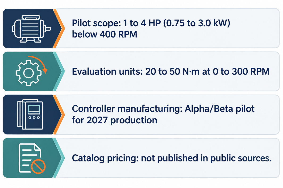
As of late 2026, C-Motive specifies its ZeroMag motor platform for 1 to 4 HP (0.75 to 3.0 kW) direct drives below 400 RPM, while its drive controller is in Alpha/Beta pilot manufacturing. Catalog prices for complete electrostatic motors weren’t found in public sources.
According to C-Motive Technologies’ product specifications and Control Engineering, early evaluation units deliver 20 to 50 N·m of torque at 0 to 300 RPM. Low-speed conveyors, mixers, and positioning tables are some targeted applications. Those direct drives replace geared conveyor motors that average 65% system efficiency. Note that the vendor-reported <0.2% power figure applies strictly to 0 RPM zero-speed holding power, where shaft output power is zero.
When Will Macro-Scale Electrostatic Motors Reach Volume Commercial Production?
As per the July 8, 2026 press release, Richardson Electronics will offer design-for-manufacturing, Alpha and Beta pilot production, and volume manufacturing services for C-Motive’s ZeroMag drive controller, and will be ready to support commercial production in calendar year 2027.
Procurement teams should keep two practical boundaries in mind during 2026 reviews. First, published performance figures are from C-Motive and UW-Madison test benches. Second, announcements don’t list catalog prices per kW or unit pricing for ZeroMag motors.
| Readiness Dimension | 2026 Verified Status for Liquid Electrostatic Motors | Procurement Implication for Plant & OEM Buyers |
|---|---|---|
| Drive Controller Manufacturing Stage | DFM & Alpha/Beta pilot production for ZeroMag drive controller (Richardson Electronics July 8, 2026 release) | Controller preparing for calendar 2027 commercial production; complete motor is not an off-the-shelf catalog spare part in 2026 |
| Power & Speed Envelope | Pilot targets: 1–4 HP (0.75–3.0 kW); reported evaluation torque: 20–50 N·m at 0–300 RPM | Obtain model-specific continuous torque, speed, and shaft-power ratings; these figures do not establish one combined operating envelope |
| Drive Electronics | Proprietary 2.5–5 kV-rms low-current CSI / 4.5 kV IGBT controller fed by plant AC power | Cannot be driven by a standard third-party 480 V VFD without the vendor’s matched controller |
| Pricing & Lead Time | No public catalog price list published in vendor or manufacturing releases | Specify IEC IE3/IE4 induction or synchronous reluctance motors for standard pump project timelines |
Which Industrial Pump Applications Could Fit an Electrostatic Drive, and Why Do Centrifugal Pumps Still Need Induction Motors?
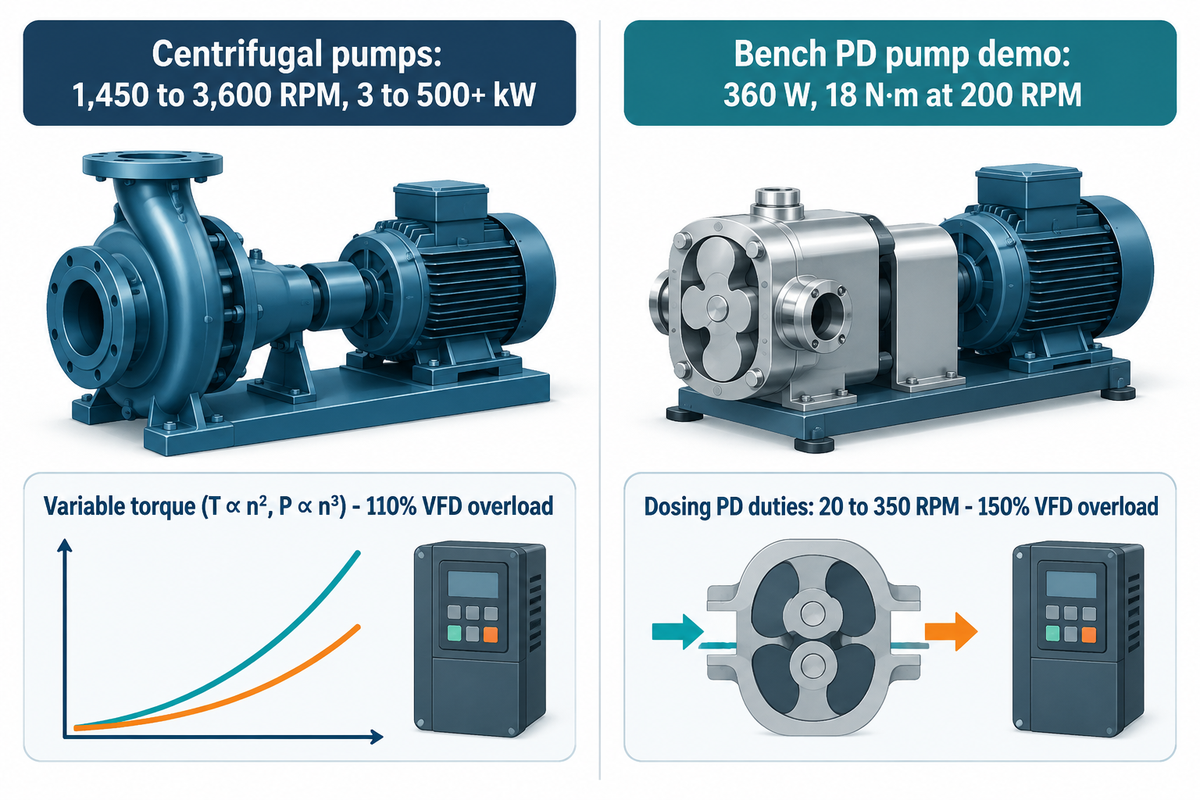
C-Motive describes ZeroMag motors as low-speed direct drives rated at 1 to 4 HP and under 400 RPM, with applications including conveyors, mixers, and positioning tables. Pump drive requirements vary by pump type and duty point. The examples below include centrifugal pumps at 1,450 to 3,600 RPM and 3 to 500+ kW, and heavy-duty slurry pumps at 600 to 1,800 RPM and 15 to 800+ kW. Small centrifugal pumps can require less than 15 kW, while large axial-flow pumps can operate below 1,450 RPM. Coupling a sub-400 RPM motor to a high-speed centrifugal pump would require a step-up gearbox, adding mechanical loss.
Some online summaries misrepresent multi-megawatt electromagnetic gearless ring motors as capacitive electrostatic motors. During lab testing, UW, Madison and C-Motive researchers coupled a 360 W, 18 N·m, 200 RPM electrostatic motor (approximately 377 W of calculated shaft output) to a low-speed hydraulic positive-displacement pump. That laboratory bench demonstrator is distinct from commercial plant trials. Positive-displacement dosing, peristaltic, progressive-cavity, and rotary-lobe duties typically require 150% VFD starting overload for 60 seconds, forced-air or TENV thermal ratings below 15 Hz, and verified washdown sealing.
Why Do Centrifugal and Positive-Displacement Pumps Demand Opposite Drive Characteristics?
In friction-dominated systems at approximately constant efficiency, centrifugal pump torque rises approximately with speed squared (T ∝ n²) to build impeller head. For fixed-displacement positive-displacement pumps moving a fixed volume per revolution at constant differential pressure and approximately constant mechanical efficiency, torque is approximately constant. Starting, acceleration, and process torque determine the required drive overload capacity, and the Malloy Electric VFD Selection Guide notes typical 110% (variable-torque) versus 150% (constant-torque) 60-second VFD overload classes:
- Variable-torque centrifugal, booster, and slurry pumps scale impeller head with speed squared and hydraulic power with the speed cubed (P ∝ n³). Standard booster pipeline pumps and slurry pumps rely on electromagnetic motors sized by the pump power formula (Ps = ρgQH / ηp). Normal-duty centrifugal VFDs commonly provide 110% overload for 60 seconds, while heavy-duty slurry drives use 150% overload.
- Constant-torque positive-displacement duties (20 to 350 RPM for dosing and peristaltic pumps) move a fixed fluid volume per revolution and commonly specify 150% VFD overload for 60 seconds during startup. Per Motion Industries, for a shaft-mounted cooling fan operating under similar conditions, airflow is approximately proportional to speed, so operation at 50% speed produces roughly 50% airflow. Full-torque TEFC operation below 15 Hz risks overheating without forced ventilation or a cartridge seal direct drive.
| Pump Category & Model Type | Typical Shaft Speed & Power | Torque-Speed Law & Overload Basis | ZeroMag Electrostatic Pilot Compatibility (1–4 HP, <400 RPM) | Recommended Commercial Drive Today |
|---|---|---|---|---|
| End-Suction Centrifugal Process Pumps | 1,450–3,600 RPM; 3–160 kW | Variable torque (T ∝ n², P ∝ n³); normal-duty VFD rating | Outside ZeroMag 400 RPM speed & 3 kW power range | IEC 60034-30-1 IE3/IE4 Induction or IE4/IE5 Synchronous Reluctance + VFD |
| Multistage High-Pressure Booster Pumps | 2,900–3,600 RPM; 5.5–500+ kW | Variable torque on friction curves; high static-head floor | Outside ZeroMag 400 RPM speed & 3 kW power range | IE3/IE4 2-Pole Induction Motor or Synchronous Reluctance + VFD |
| Heavy-Duty Mining Slurry & Gravel Pumps | 600–1,800 RPM; 15–800+ kW | High breakaway torque + variable running load; heavy-duty VFD rating | Incompatible: power demand ranges from 5 times to more than 266.7 times the 3 kW pilot ceiling | IE3/IE4 Inverter-Duty Induction Motor + VFD or Belt/Gearbox |
| Submersible Sewage & Wastewater Pumps | 960–1,800 RPM; 2.2–250 kW | Variable torque with solids-passage starting surge | Outside ZeroMag speed range & requires submerged motor enclosure | Hermetically Sealed Submersible IE3/IE4 Induction Motor |
| Large Axial-Flow & Mixed-Flow Flood Pumps | 300–1,450 RPM; 30–1,000+ kW | Variable torque with high shutoff power; multi-pole or geared | Outside ZeroMag 3 kW power ceiling by 10× to 333× | Multi-Pole IEC Induction Motor or Medium-Voltage Synchronous Drive |
| Hydraulic Positive-Displacement Bench Pump | 200 RPM test point; 360 W (~377 W shaft output) | Constant torque at fixed differential pressure (18 N·m test) | Bench-demonstrated on hydraulic PD pump (360 W, 18 N·m at 200 RPM, ~377 W calculated shaft output) | Inverter-Duty TEFC/TENV Gearmotor or PM Torque Motor |
| Small Chemical Metering & Peristaltic Dosing Pumps | 20–350 RPM; 0.25–2.2 kW | Constant torque at constant Δp; heavy-duty starting torque | Candidate for low-speed direct-drive pilot qualification | Inverter-Duty TEFC/TENV Motor + Gear Reducer or Stepper/Servo |
| Sanitary Rotary Lobe & Progressive Cavity Pumps | 50–350 RPM; 0.75–3.0 kW | Constant running torque + high viscous breakaway torque | Candidate for pilot evaluation once washdown sealing is verified | Washdown Inverter-Duty Gearmotor or Direct PM Synchronous Drive |
| Low-Shear Tank Agitators & Industrial Mixers | Application-specific low RPM; 0.75–3.0 kW | Speed-dependent mixing torque: approximately proportional to speed squared (n²) in turbulent flow and to speed (n) in laminar flow; zero-speed holding is a separate drive capability | Named application for C-Motive ZeroMag 1–4 HP direct-drive pilots | Helical-Bevel Gearmotor or Direct-Drive PM Synchronous Motor |
How Should Engineers Select Motor Drives for Industrial Pump Skids Today?
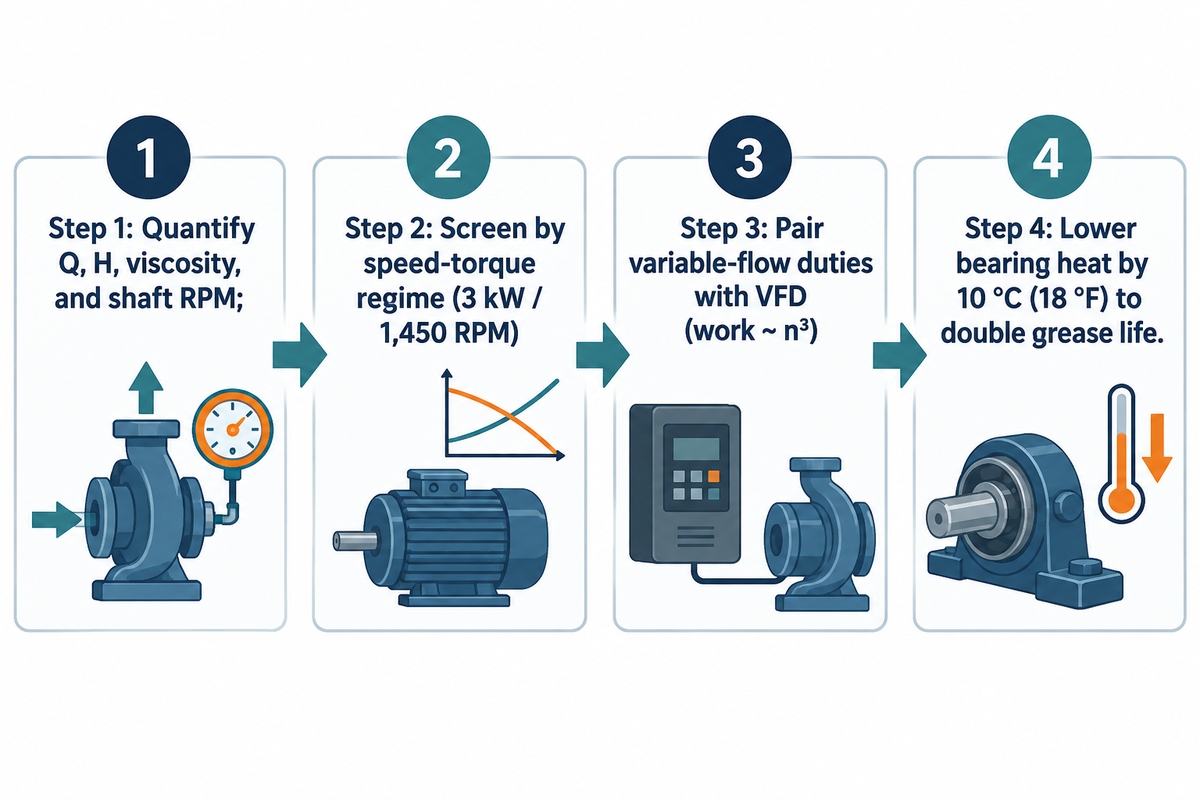
For industrial pump skids in 2026, select line-fed AC induction motors under IEC 60034-30-1 or converter-fed variable-speed motors under IEC TS 60034-30-2:2016, using the four-step selection workflow described below. The cited IEC standards classify motor efficiency; cooling and duty ratings govern thermal performance, while matching mechanical and electrical interfaces enables spare-part interchangeability.
- Step 1 (Quantify Duty-Point Shaft Power and Speed) requires a complete pump sizing calculation for Q, H, specific gravity, viscosity, and shaft RPM for all pumps operating on clean water, chemicals, and sewage.
- Step 2 (Screen by Speed-Torque Regime) defines standard IEC or NEMA electromagnetic motors for centrifugal, axial-flow and slurry pumps. That includes low-power centrifugal pumps from 3 kW and low-speed slurry or axial-flow pumps below 1,450 RPM. For 20 to 350 RPM dosing pumps under 3 kW, use an inverter-duty gearmotor today and track electrostatic direct-drive pilots.
- Step 3 (Pair Variable-Flow Duties with an Inverter-Duty VFD) applies a VFD drive to a pump to realize cubic affinity-law energy savings (pump work ~ n³ on friction-dominated curves). The Hydraulic Institute VFD guide has information on variable-torque sizing.
- Step 4 (Verify IEC Efficiency Class and Thermal Margin) checks compliance with pump industry standards (HI, ISO, API, ASME) and monitors bearing heat. Per Hydraulic Institute data, lowering motor bearing temperature by 10 °C (18 °F) doubles grease life.
What Should Pump Engineers Specify Today If They Want Magnet-Free High Efficiency?
Pump engineers seeking IE4 or IE5 permanent-magnet-free efficiency today should specify a converter-fed synchronous reluctance motor under IEC TS 60034-30-2:2016 or a line-fed IE4 induction motor under IEC 60034-30-1. According to 4Q Systems’ IEC 60034-30-1 reference, upgrading a 4-pole, 50 Hz motor from IE3 to IE4 raises efficiency from 90.4% to 92.6% at 7.5 kW. It also raises efficiency from 93.9% to 95.2% at 37 kW and from 95.0% to 96.0% at 75 kW.
Frequently Asked Questions
Are there electromagnets in an electric motor?
Conventional industrial electric motors—including AC squirrel-cage induction, brushed DC, and wound-field synchronous units—use copper-wound electromagnets to produce Lorentz force. By contrast, an electrostatic motor replaces magnetic wire coils with closely spaced electrode plates of a capacitor driven by a kilovolt electric field and Coulomb charge attraction, and piezoelectric actuators operate without electromagnets.
Is a magnet-free motor possible?
A number of permanent magnet-free motor architectures are operating or in pilot deployment in industrial plants. For example, squirrel cage induction and synchronous reluctance motors use electromagnetic fields to operate permanently magnet-free. Meanwhile, C-Motive’s liquid-dielectric electrostatic motors eliminate rare-earth permanent magnets and cut copper usage by 90% in low-speed direct drives.
What is a stator electric motor?
In an induction motor, the stator is made of laminated steel and contains copper windings. In a liquid-dielectric electrostatic motor, the stator can consist of circuit-board electrodes submerged in dielectric fluid. In both motor architectures, the stationary stator assembly surrounds or faces the moving rotor across a narrow gap and applies the alternating electric or magnetic field that generates shaft torque.
Can an electrostatic motor run on standard 240V or 480V plant power?
Industrial liquid-dielectric electrostatic motors accept standard AC plant power. They connect to the plant supply through integrated solid-state drive enclosures. Internal power electronics step up the input supply to kilovolt electrode pulses while drawing only milliamps of phase current.
How does dielectric fluid maintenance work inside a macro-scale electrostatic motor?
Macro-scale liquid-dielectric electrostatic motors require inspection of rotary shaft seals and intermittent checks of capacitance. Sealed housings help protect dielectric fluid from external contamination, but internally generated bubbles, wear particles, and assembly residues can still reach the electrode gaps. Keeping fluid conductivity at or below 10⁻¹⁰ S/m limits leakage-current heating; at a fixed conductivity, the remaining heating increases with the square of the electric field.
What are examples of electric motors that do not use rare-earth magnets?
Industrial pump and machinery electric motors that don’t use rare earth permanent magnets include three phase squirrel cage induction motors, synchronous reluctance motors, and switched reluctance motors (SRM), ferrite-magnet PMSM and emerging low speed liquid-dielectric electrostatic motors.
Does BBP manufacture electrostatic motors or supply standard pump drive packages?
BBP Manufacturing Co., Ltd. does not design, manufacture or sell electrostatic motors. Our factories build industrial centrifugal, slurry, axial-flow and submersible pumps engineered around proven IEC and NEMA electromagnetic drive systems. Our application engineers help plant operators size complete pump-and-motor skids using IE3, IE4 and VFD-controlled induction or synchronous reluctance motors. Standardizing on IEC frame dimensions and rated cooling enclosures supports mechanical cartridge seal access and global spare-parts support without relying on experimental drive prototypes.
References & Sources
- Daniel C Ludois et al. (2022). Macroscale Electrostatic Rotating Machines and Drives: A Review and Multiplicative Gain Performance Strategy. IEEE Journal of Emerging and Selected Topics in Power Electronics, 10(1), 539-556.
- University of Wisconsin, Madison WEMPEC. Professor Daniel Ludois Electric Machines Laboratory Overview & WEMPEC Research Interests.
- Daniel C Ludois et al. / Wisconsin Alumni Research Foundation (2021). USPTO Patent US10958191B2: Electrostatic Machine and Dielectric Fluid System.
- Hydraulic Institute (2024). Driver Technology for Variable Speed Applications & Pump Pros Know: Variable Frequency Drives.
- Richardson Electronics, Ltd. (July 8, 2026). Richardson Electronics Selected to Manufacture Power Supply for C-Motive’s New ZeroMag Electrostatic Motor.
- Control Engineering. New Electrostatic Motor Design: 90% Less Copper, No Magnets, Ultra-Efficiency.
- Wiley Advanced Intelligent Systems (2023). Electrostatic Actuators and Maxwell Stress Scaling Across Dielectric Gaps (DOI: 10.1002/aisy.202200425)
- 4Q Systems. What Is IE3 and IE4 Motor Efficiency Under IEC 60034-30-1?
- Malloy Electric & Motion Industries. Variable Frequency Drive Selection Guide (Variable vs. Constant Torque) & 5 VFD Myths You Need to Watch Out For (TEFC 15 Hz Cooling Limit).
WHY BUYERS WORK WITH BBP
About BBP Manufacturing
BBP Manufacturing Co., Ltd. is a Beijing-based industrial pump manufacturer with in-house foundry, heat treatment, machining, assembly, coating and inspection capabilities. We support industrial projects across slurry handling, sewage treatment, clean water transfer, chemical service, fire protection, irrigation and OEM pump supply.
Our Engineering Support
We help engineering buyers select and source the right pump configuration, not just compare prices. Send us your flow rate, head, medium, solids content, temperature, pH value, material requirement and installation conditions. BBP engineers will recommend a pump series, material option, duty curve basis, lead time and spare-parts plan for your RFQ.
Company Profile // DATA_SHEET
Name
BBP Manufacturing Co., Ltd.
Brand Name
BBP
Country
China
Headquarters
Beijing, P.R. China
Business Type
Industrial Pump Manufacturer
Model
B2B / OEM / ODM / Project Supply
Main Products
Slurry Pumps, Sewage Pumps, Centrifugal Pumps, Split Case Pumps, Multistage Pumps, Chemical Pumps, Fire Pumps, Irrigation Pumps
Manufacturing Capability
Foundry, Heat Treatment, Machining, Assembly, Coating, Inspection
Certifications
ISO 9001 / CE / SGS / BV / TÜV
Export Reach
90+ Countries & Regions
Standard Lead Time
About 25 Days for Standard Configurations
Contact Person
Wesley · International Sales
Phone / WhatsApp
+86 182 1085 0516
Email
contact@bbpmfg.com
Website
https://bbpmfg.com/
Address
Room 2803, Building 11, Phase II, Nuode Center, Fengtai District, Beijing, P.R. China
Related Posts
Trending now