Get in Touch with BBP

By CYH, Rotating Equipment & Foundry Engineering Specialist at BBP Manufacturing Co., Ltd. | Updated November 2026 | Technical Standards: ANSI/HI 14.1-14.2, ANSI/HI 14.3, ISO 9906:2012, ISO 21940-11:2016, API 610
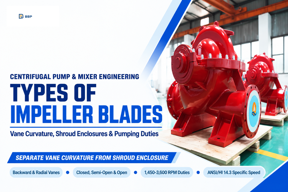
The types of impeller blades are determined by separating the three mechanical variables which supplier catalogs often combine. Engineers must specify blade vane curvature, shroud enclosure, and flow discharge profile independently. A centrifugal pump impeller is the rotating component that transfers mechanical energy from the drive shaft. How those impeller vanes curve governs pressure recovery while front and back shrouds control pump efficiency, solids handling, and suction performance. Choosing the right impeller prevents chronic clogging, motor breaker trips, and cavitation erosion.
Key Engineering Takeaways: Types of Impeller Blades at a Glance
- Always separate vane curvature (backward-curved, radial, forward-curved, and twisted Francis) from shroud structure (closed, semi-open, and open). Then match specific speed flow patterns.
- Closed impellers deliver the highest clean-water hydraulic efficiency at 20 °C (68 °F) per Hydraulic Institute standards. Semi-open and open designs trade peak efficiency for wider solids passage.
- Recessed vortex impellers keep radial blades out of the primary slurry path to cut abrasive contact wear, though their turbulent whirlpool motion consumes more shaft power than enclosed channel rotors.
- Per Hydraulic Institute ANSI/HI 14.3, radial flow impellers run below 4,500 US units (7,000 US double suction). Mixed flow spans 4,500 to 10,000 US, and axial flow exceeds 10,000 US (ANSI/HI 14.3).
- Field lathe trimming should never exceed a 15% diameter reduction per Heinz Bloch’s impeller trimming rules, and vane trailing edges must retain at least 8 mm tip thickness.
How an Impeller Works: Separating Blade Vane Geometry from Shroud Enclosure
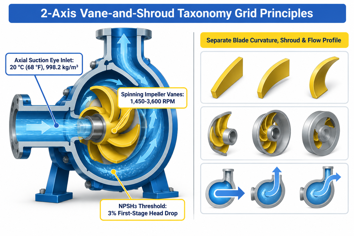
To know the different types of impellers, engineers trace how an impeller works inside a pump casing. Liquid enters the low-pressure suction eye axially near the shaft hub. The spinning impeller has vanes that accelerate fluid via centrifugal force into the volute to build pressure head across the pump’s range.
According to the Hydraulic Institute ANSI/HI 14.1-14.2 Table of Definitions, standard hydraulic curves use clean water at 20 °C (68 °F) with a reference density of 998.2 kg/m³. As stated in BBP Manufacturing’s rotor balancing engineering guide, most industrial centrifugal pumps operate at 1,450-3,600 RPM on 4 or 2-pole motors. When the absolute inlet pressure drops below the vapor pressure, cavitation bubbles are formed and collapse on a metal surface. According to the Hydraulic Institute NPSH3 standard, the net positive suction head required is the suction threshold at which first stage head drops by 3% due to cavitation in the eye of the pump.
Buyers frequently treat shroud enclosure and blade shape as a single list, which results in purchase order failures. Saying a particular unit uses an open impeller or a closed impeller only describes the side plates. It doesn’t describe the impeller’s blade exit angle or flow path. Our 2-Axis Vane-and-Shroud Taxonomy Grid, below, differentiates the main types of impellers and the main impeller types across ten distinct rotor configurations. Engineers comparing industrial centrifugal pump configurations across horizontal and vertical frames use this grid to identify pump and impeller specifications early.
| Impeller Blade Type & Category (2-Axis Vane-and-Shroud Taxonomy Grid) | Shroud Enclosure Structure | Vane Curvature & Flow Vector | Hydraulic & Solids-Handling Profile |
|---|---|---|---|
| Closed Backward-Curved Radial Impeller | Dual Shroud (Front & Back Plates) | Backward-swept radial discharge | Highest clean-water BEP efficiency; non-overloading motor power curve for clean process liquids. |
| Semi-Open Backward-Curved Process Impeller | Single Back Shroud (Exposed Front Vanes) | Backward-swept radial discharge | Moderate efficiency; passes light industrial slurries with external axial face-clearance adjustment. |
| Open Backward-Curved Utility Impeller | Central Hub Only (No Shroud Plates) | Backward-swept unshrouded blades | Lower clean-water efficiency due to dual-face tip spill; releases fibrous pulp and stringy debris easily. |
| Closed 3D Twisted Francis-Vane Impeller | Dual Shroud (Single or Double Suction) | Axial entry to 60°–70° exit angle (ANSI/HI 14.1-14.2) | Low-NPSH suction performance and high-flow double-suction split-case water service. |
| Semi-Open Mixed-Flow Bowl Impeller | Single Back Shroud in Diffuser Bowl | 45° diagonal discharge (ANSI/HI 14.1-14.2) | Bridges radial head and axial flow for vertical turbine irrigation and stormwater drainage stations. |
| Open Axial-Flow Propeller Impeller | Unshrouded Hub in Pipe Casing | Twisted airfoil blades (parallel axial flow) | High-volume flood control and evaporator circulation above Ns = 10,000 US (ANSI/HI 14.3). |
| Recessed Vortex Radial-Blade Impeller | Recessed Back Disc in Volute Cavity | Straight radial or cast ribs | Creates free whirlpool away from main flow path; ideal for heavy grit and crystalline sludge. |
| Enclosed Non-Clog Channel Impeller | Dual Shroud Wide-Passage Rotor | 1 to 3 deep backward-curved channels | Passes large wastewater spheres while retaining closed-shroud energy efficiency on continuous lift stations. |
| Helicoidal Screw-Centrifugal Impeller | Open or Semi-Open Conical Hub | 3D spiral corkscrew inducer + radial exit | Ultra-low shear handling for thick biological floc, delicate food solids, and viscous polymer slurries. |
| Open-Tank Pitched & Rushton Mixer Blades | Unshrouded Vessel Agitator Hub | 45° pitched blade or flat radial disc | Open-vessel chemical blending, solids suspension, and gas dispersion without a pump volute. |
What is the main difference between a propeller and an impeller?
A propeller is an unshrouded axial rotor operating in an open tank or tube to produce thrust parallel to the axis of rotation. An impeller is a casing-enclosed rotor in a pump or mixer. It employs controlled clearances to build static pressure and volume flow.
In everyday shop parlance, pumps with axial flow impellers inside vertical flood-control pipe casings are often called propeller pumps. True pump impellers rely on tight pump casing boundaries and volute geometry to develop hydraulic head.
Blade Curvature Types: Backward-Curved, Radial-Straight, Forward-Curved, and 3D Twisted Vanes
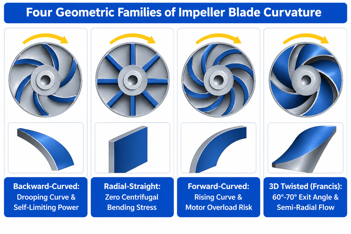
The curvature of impeller vanes with respect to rotation controls the Euler velocity triangle at the outer rim. As liquid leaves blade tips, its tangential and radial vectors determine the static head to velocity head ratio. Engineers classify centrifugal pump impeller blades into four geometric families based on discharge curvature and spatial twist.
Of the four geometric families of centrifugal pump impeller blades, this common impeller backward-curved geometry is commonly used in centrifugal water, chemical and slurry services. Relative fluid velocity opposes peripheral tip speed, and as flow rate increases, backward-curved vanes create a stable drooping head-capacity curve. In addition, backward-curved impellers can have a self-limiting brake horsepower curve. Should a discharge valve be fully opened, the motor power peak occurs at the best efficiency point (BEP) and limits the over speed condition.
Radial-straight blades extend straight outward from the central hub, like wheel spokes. Their mass is aligned directly with the centrifugal force vector, eliminating bending stress from centrifugal loading at high rotational speeds. They are mainly found in recessed vortex slurry rotors, high speed bars and tank radial turbines. Forward-curved blades are used in high velocity compact air blowers. However, forward-curved blades on liquid pump motors result in a rising curve, overloading the motor at high flow.
3D twisted Francis vanes smoothly connect an axial inlet angle at the eye to a semi-radial discharge. According to the Hydraulic Institute ANSI/HI 14.1-14.2 standard, a Francis-vane impeller receives liquid axially and exits semi-radially at around a 60° to 70° angle to the shaft axis. A 2025 study published in the International Journal of Heat and Fluid Flow tested 2D cylindrical blades against 3D twisted blades at 1,450 RPM. The 3D twisted blades delivered higher single-phase part-load efficiency and superior gas handling at high overload. On the other hand, the 2D cylindrical blades suppressed flow surging more effectively during two-phase part-load conditions.
The surface finish of the blade is just as critical as its geometric curvature. A 2025 study in the MDPI Machines measured the roughness of sand cast GG-18 blades at Ra = 81.72 μm and CNC machined Ra = 1.276 μm. In the same 2025 MDPI Machines impeller study, the smooth 3D-printed composite impeller was 9 dB quieter than the original cast iron pump, which operated at 83 dB.
| Blade Curvature Profile | Vane Geometry & Flow Vector | Power Curve Behavior | Primary Industrial Pump Application |
|---|---|---|---|
| Backward-Curved Blades | Swept opposite to rotation; smooth hydraulic diffusion channel. | Non-overloading beyond BEP; highest static pressure recovery. | Clean water, chemical process, multistage boiler feed, and slurry pumps. |
| 3D Twisted Francis Vanes | Axial entry with 60° to 70° exit angle (ANSI/HI 14.1-14.2). | Non-overloading; superior single-phase part-load and high-gas overload handling. | Low-NPSH suction stages, double-suction split-case, and mixed-flow pumps. |
| 2D Cylindrical / Radial Blades | Zero axial twist or straight radial spokes; resists centrifugal bending. | Flat head curve; suppresses surging in two-phase part-load operation (IJHFF 2025). | Recessed vortex wastewater pumps, high-speed bars, and Rushton agitators. |
| Forward-Curved Blades | Curved into rotation; maximizes kinetic velocity head over static head. | Steeply rising overloading power curve as discharge resistance falls. | Centrifugal air blowers and current-limited regenerative boosters. |
Shroud Enclosure Types: Closed, Semi-Open, and Open Impeller Trade-Offs
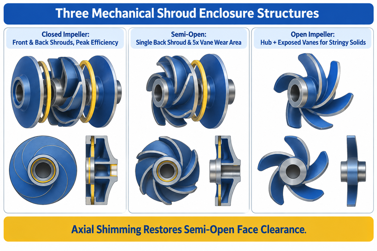
After blade curvature is chosen, engineers need to determine the best shroud enclosure for the liquid and its suspended solids. In centrifugal pump design, the three types of mechanical shroud structures-closed, semi-open and open-govern the stiffness of the structure, fluid recirculation leakage and the risk of clogging.
A closed impeller features front and back shrouds that enclose the impeller vanes from the suction eye to the outer rim. Because the shroud adds mechanical strength to the vanes, closed rotors can handle high discharge pressures without blade deflection. Fluid cannot spill over the vane tips, and leakage is limited to the radial wear ring. Thus, a closed impeller has the best hydraulic efficiency for a shroud design. Enclosed channels can, however, trap fibrous rags unless sized as wide-passage sewage channels.
A semi-open impeller has no front shroud and consists of vanes attached to a back shroud. Open design on the suction side exposes the blade edges to the pump casing wear plate and passes moderate industrial slurries without bridging. As reported on Eng-Tips Pump Forums semi-open impellers provide roughly 5 times the wear surface area across their vane edges compared to a wear ring. When the clearance between the vanes and casing wall is opened by an abrasive slurry, technicians shim the shaft axially to close the clearance, in an attempt to restore operating pressure.
open impeller consists of vanes attached directly to the central hub, placing the blades completely open with vanes that are open on both sides. Because the design allows fibrous and raggy solids to pass, each open impeller used resists stringy clogging across different impeller sizes. An open rotor has lower clean-water efficiency compared to a closed rotor due to tip recirculation on both sides. Yet in service with slightly abrasive water over a long period, an axially adjusted open or semi-open impeller holds its curve better compared to a worn closed impeller with worn wear rings. Plant engineers considering single-stage end-suction centrifugal pumps with closed and semi-open impellers should consider trade-offs of multi-year clearance wear against Day-1 catalog efficiency.
⚠️ Engineering Scope Limitation: Clean-Water Efficiency Baselines
Catalog peak hydraulic efficiency ratings for open, semi-open, and closed impellers are assessed in test stands using clean water at 20 °C (68 °F) in accordance with Hydraulic Institute standards. Actual field efficiency decreases significantly when pumping fluids of high viscosity or dense abrasive slurries.
| Parameter | Closed Impeller (Dual Shroud) | Semi-Open Impeller (Back Shroud) | Open Impeller (Hub + Exposed Vanes) |
|---|---|---|---|
| Clean-Water Hydraulic Efficiency | Highest (dual-shroud hydraulic containment) | Moderate (single-face tip clearance spill) | Lowest (dual-face unshrouded recirculation) |
| Wear Surface Area | Concentrated at narrow radial wear ring | 5 times the wear area across vane edges (Eng-Tips) | Exposed front and rear blade edges |
| Solids & Fiber Handling | Clean liquids (or wide channel sewage rotors) | Moderate industrial slurries and fine grit | Stringy fibers, pulp, and utility dewatering |
| Wear Restoration Method | Pump disassembly & wear-ring replacement | External axial shaft adjustment (10mm slot per CN111536050A) | Axial wear-plate shimming |
Are semi-open and semi-closed impellers the same thing?
Yes, semi-closed impeller and semi-open impeller designations refer to the same rotor configuration. Both descriptions are used to define a pump impeller built with a single solid back shroud supporting the vanes on the drive side. The front suction face is unshrouded, and is in direct contact with the casing wear plate.
North American standards such as ANSI/HI 14.1-14.2 prefer the term semi-open impeller. Several European and sanitary pump catalogs list the same single-shroud configuration as semi-closed.
Flow Direction Profiles: Radial, Mixed-Flow, Axial, and Double-Suction Impellers by Specific Speed
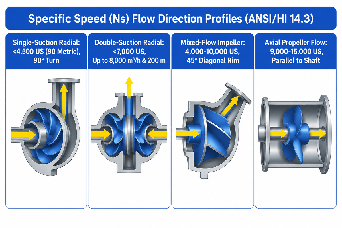
Besides blade curvature and shrouds, all pump impellers are defined by their specific speed (Ns). Specific speed is a ratio that ties the flow, total head at BEP and rotational speed. Specific speed increases cause the outer impeller diameter to shrink relative to the suction eye. Simultaneously the discharge flow patterns shift from radial to mixed-flow and then to axial.
Under Hydraulic Institute ANSI/HI 14.3 , single-suction radial flow impellers operate at specific speeds below 4,500 US units (90 metric), and double-suction rotors below 7,000 US (135 metric). Radial-flow pumps are classified by UF/IFAS Publication WI001 at 5,000 US or below (excluding 5,000 US), mixed-flow at 4,000 to 10,000 US and axial-flow at 9,000 to 15,000 US. In a radial impeller, liquid enters the suction eye axially and turns 90° to leave the impeller perpendicular to the shaft.
When a single radial stage requires a narrow pancake rotor, disk friction losses quickly increase. Adding a stage increases head, but not necessarily value. Operating outside the optimal specific-speed band sacrifices hydraulic efficiency on every stage. Therefore, engineers specify high-pressure multistage centrifugal pumps with series-mounted closed impellers only after matching duty flow, NPSH available, and liquid temperature. On the other hand, high flow and low suction pressure require a larger inlet area. In such cases, double-suction split-case pumps for high-flow axial-balanced duties are designed with two back-to-back radial inlets on a single rotor. Per BBP Manufacturing’s split-case pump specifications, horizontal double-suction pumps (S/SH/XS series) deliver flow rates up to 8,000 m³/h and heads up to 200 m while neutralizing axial thrust.
The mixed-flow impeller occupies the intermediate specific-speed band. As per the Hydraulic Institute Table of Definitions, a mixed-flow impeller has a single inlet with flow entering axially and discharging at about a 45° angle to the shaft axis. Engineers sizing agricultural and municipal water stations can review our mixed-flow irrigation pump hydraulics and specific-speed selection guide for bowl assembly curves. At the upper end of the specific-speed spectrum, an axial flow impeller (propeller pump) is used to move high flows in parallel to the shaft with low static head. Our Specific-Speed & Solids-Passage Crossover Table relates these various hydraulic regimes with suction and cavitation.
⚠️ Engineering Scope Limitation: Opposite Cavitation Zones in Radial vs. Axial Impellers
According to UF/IFAS Extension Publication WI001, both radial-flow and mixed-flow impellers experience cavitation at high flow rates when the head drops far below BEP. Axial-flow propeller impellers, however, can experience cavitation at low flow rates, where the discharge head rises above the head at their BEP.
| Specific-Speed & Solids-Passage Crossover Table | US Specific Speed (Ns) Range | Discharge Angle to Shaft | High-Risk Cavitation Zone | Typical Pump Architecture |
|---|---|---|---|---|
| Radial-Flow Impeller (Single Suction) | < 4,500 US (ANSI/HI 14.3) / < 5,000 US (UF/IFAS) | Perpendicular radial exit | Low head / runout high flow | End-suction process & multistage ring-section pumps |
| Francis-Vane / Double-Suction Radial | < 7,000 US double suction (ANSI/HI 14.3) | 60° to 70° semi-radial (ANSI/HI 14.1) | Low head / high flow | Horizontal double-suction split-case water transport pumps |
| Mixed-Flow Impeller | 4,000 to 10,000 US (UF/IFAS) | About 45° diagonal (ANSI/HI 14.1) | Far below BEP head | Vertical turbine bowl & drainage irrigation pumps |
| Axial-Flow Propeller Impeller | 9,000 to 15,000 US (UF/IFAS) | Parallel to shaft axis | High head / throttled discharge | Flood control, evaporator circulation & axial dewatering |
How do I know if an impeller creates a radial flow or an axial flow?
Compare the outer rim of the blades against the suction eye. A radial flow impeller, has a wide outer rim which throws liquid outward, perpendicular to the shaft. An axial flow impeller, however, uses propeller blades to push liquid in the same direction, parallel to the shaft.
If the rotor’s outer rim slopes diagonally at about 45 degrees (ANSI/HI 14.1-14.2) and the rotor discharges into a bowl diffuser rather than a scroll volute, it is a mixed-flow impeller.
Non-Clog & Specialty Impeller Blades: Vortex, Cutter, Screw, Channel, and Flexible Vanes
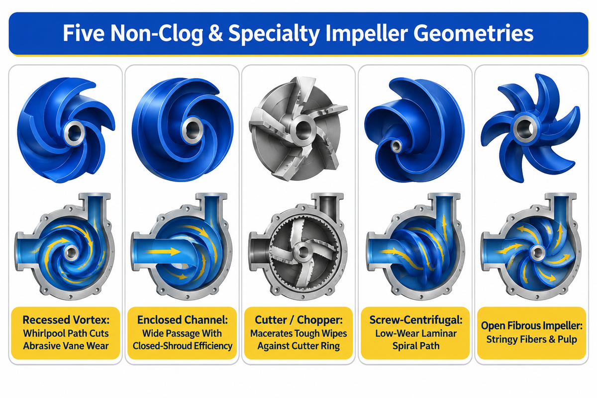
Municipal wastewater, mining tailings and food processing waters contain rags, abrasive grit and shear-sensitive solids, which quickly plug radial vanes. For these services, pump impeller types evolved into five specialized non-plugging geometries: vortex, channel, cutter, screw-centrifugal and flexible vane impellers.
The vortex impeller (recessed impeller) is positioned within the rear of the volute case. Radial vanes are out of the main liquid path. The recessed rotor creates a free whirlpool (solid body rotation) effect in the cavity of the case. Most solid particles sweep from suction to discharge without striking the metal vanes. Consequently, the wear of the vanes is significantly reduced, and the service life of the rotor is extended, in heavy grit and sludge duties. The trade off is hydraulic turbulence. Vortex impellers have lower energy efficiency compared to open and channel models and require a higher NPSH to operate at high flow. For dewatering selection details, see our non-clog centrifugal trash pump vs. standard dewatering pump comparison.
Continuously operating lift stations often cannot afford the electricity penalty of a vortex rotor. In these stations, engineers specify a single- or dual-vane channel impeller. Its wide closed channels, pass large wastewater solids, while maintaining closed shroud efficiency. If unscreened sewage contains tough wet wipes and plastics, a cutter impeller (chopper pump) is recommended. Per Hydraulic Institute wastewater pump guidelines, chopper and cutter impellers macerate stringy debris against a stationary cutter ring, before it enters the volute.
For shear-sensitive activated sludge, live fish or food mash, engineers use a helicoidal screw impeller. It consists of a corkscrew-type positive displacement inducer and a single vane discharge. The gentle spiral channel prevents breakage of flocs and handles high-viscosity products without emulsifying them. Low volume sanitary transfers employ a flexible impeller. It is made from neoprene or EPDM elastomers. For slow speed operation, its flexible blades self prime and pump suspended solids and viscous liquids.
⚠️ Engineering Scope Limitation: Vortex Impeller Ragging & Power Penalty
Recessed vortex impellers reduce blade contact wear in abrasive grit slurries. However, single vane vortex chambers can bind on long, fibrous rags in unscreened sewage and carry an energy efficiency penalty that makes them uneconomical for high-flow, clean water transfers.
| Specialty Non-Clog Impeller Type | Solids & Slurry Handling | Wear & Metallurgy Profile | Fluid Shear & Efficiency Profile | Best Specific Application |
|---|---|---|---|---|
| Recessed Vortex Impeller | High-grit sludge & large solids | Longest abrasive life (minimal vane contact) | Low contact shear; higher power draw due to whirlpool turbulence | Abrasive grit, mining tailings, and crystalline sludge |
| Semi-Open Non-Clog Impeller | Moderate industrial slurries | 5 times wear area vs. wear ring (Eng-Tips) | Moderate shear; adjustable front gap restores efficiency | Industrial wastewater, coal wash, and chemical slurries |
| Open Fibrous Impeller | Stringy fibers & pulp | Exposed vanes require periodic axial shimming | Sweeping vane action; lower clean-water efficiency | Stringy wastewater, paper pulp, and sump drainage |
| Cutter / Chopper Impeller | Heavy fibrous wipes & rags | Hardened high-chrome white iron alloy cutting edges | Extreme mechanical maceration shear | Unscreened municipal lift stations and agricultural manure |
| Screw-Centrifugal Impeller | Thickened sludge & delicate solids | Low-wear laminar spiral path | Ultra-low shear; steep non-overloading curve | Biological floc, food produce, and viscous polymer slurries |
Industrial Agitator & Mixer Impeller Blades: Pitched-Blade Turbine, Rushton, Hydrofoil, and Cowles Dispersers
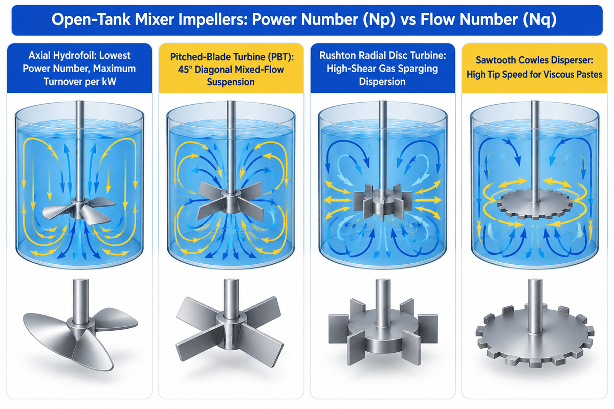
The pump impeller builds static pressure in a volute. An agitator impeller is one designed for use in a tank to circulate liquids and suspend or disperse solids. Agitator blades are rated by two dimensionless constants, Power Number (Np) and Flow Number (Nq), for turbulent mixing.
For low shear tank mixing and circulation of miscible liquids, axial Hydrofoils are used. They generate lift like an airfoil and turnover a tank with minimal shear. Of turbine mixers, axial hydrofoils operate at the lowest power number and deliver highest pumping circulation per kilowatt.
Pitched Blade Turbines (PB4 / PBT): A 4-blade pitched-blade turbine is the general-purpose workhorse of chemical reactors. Fluid is discharged at a diagonal mixed-flow angle, which balances axial circulation and provides moderate fluid shear for solids suspension and heat transfer.
Rushton Radial Disc Turbines and High-Shear Cowles Blades: For dispersing gas-bubbles or breaking up droplets, a Rushton radial disc turbine is generally used. Its radial blades, mounted on a horizontal disc, are powered by the shaft and give a high shear on gas sparging streams. For de-agglomerating pigments or breaking up higher viscosity pastes, Cowles disperser blades, with a high tip speed, are used. When the fluid viscosity increases beyond the centrifugal mixing limit to heavy pastes, consult our comparison of positive displacement vs. centrifugal pump viscosity and shear for sizing the transfer loop.
| Tank Mixer Impeller Type | Relative Power Number (Np) | Discharge Flow Vector | Shear vs. Circulation Profile |
|---|---|---|---|
| Axial Hydrofoil Impeller | Lowest power number (energy-saving axial airfoil) | Axial parallel down-pumping | Ultra-low shear; maximum bulk tank turnover per kW |
| Pitched-Blade Turbine (PBT) | Moderate power number (mixed axial/radial torque) | 45° diagonal mixed flow (ANSI/HI) | Balanced axial flow and moderate shear for solids suspension |
| Rushton Radial Disc Turbine | Highest power number (high-torque radial disc) | Perpendicular radial discharge to wall | High-shear gas sparging dispersion and emulsion breakup |
| Sawtooth Cowles Disperser / Anchor | Reynolds-number & paste-viscosity dependent | Radial high-shear / wall-scraping | High-intensity powder wet-out and higher viscosity pastes |
Blade Count (2 to 8 Vanes), Vane Pass Frequency, and Impeller Diameter Trimming Rules
How many blades should a centrifugal pump impeller have? There is a trade-off between hydraulic guidance and inlet eye blockage for vane count. Fewer vanes in sewage or trash impellers allow for a larger free passage of spheres. For smoother, guided liquids in multistage clean water impellers, more vanes are used.
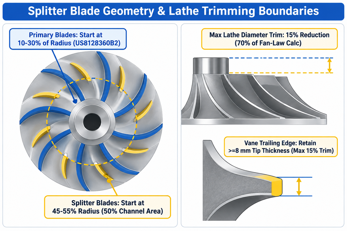
Adding longer blades to a high-head impeller eventually chokes the narrow suction eye and causes inlet cavitation. To solve this without losing outer-rim guidance, engineers insert short splitter blades between primary vanes. According to U.S. Patent US8128360B2, primary blades start at 10-30% of the radius, while splitter blades start at 45 to 55 percent of the radius (50% channel area). This splitter blade geometry prevents inlet choking and helps to stabilize discharge pressure.
In the field, if a pump produces too much head, significant power is saved by machining down the outer diameter of the impeller on a lathe. There are strict mechanical boundaries to this work, and Heinz Bloch points out in his book Empowering Pumps that a diameter reduction should not go over 15% and that in this field, a specialist should not machine deeper than 70% of the fan-law calculation. A deeper cut increases clearance between the blade tips and the volute cutwater, resulting in severe discharge recirculation.
Worked Engineering Example: Heinz Bloch 70% Conservative Trim Rule & Trailing-Edge Underfiling
To reduce head using the Euler fan law, one must determine how deep to machine and what to do with the tips of vanes.
- First, ensure the proposed diameter reduction remains within the 15% field limit established in Heinz Bloch’s Empowering Pumps guideline, because theoretical Affinity Law calculations become inaccurate with deep cuts.
- Next, following the guidance in Empowering Pumps, machine only 70% of the reduction derived from the fan-law calculation as the initial lathe cut and test-run the pump first.
- Lastly, when underfiling the trailing edge, keep tip thickness at or above 8 mm (~5/16th inch) to recover approximately 4% BEP head (Empowering Pumps).
⚠️ Engineering Scope Limitation: Affinity Law Deviation on Trimmed Impellers
The Centrifugal impeller trimming Affinity Laws apply strictly to small diameter cuts on radial-flow rotors. When diameter reductions approach the 15% field limit (Empowering Pumps) or are applied to mixed-flow impellers, theoretical predictions diverge and require manufacturer’s test curves.
Wear Ring Clearance, Axial Face Gap Adjustment, and Cavitation Damage Diagnostics
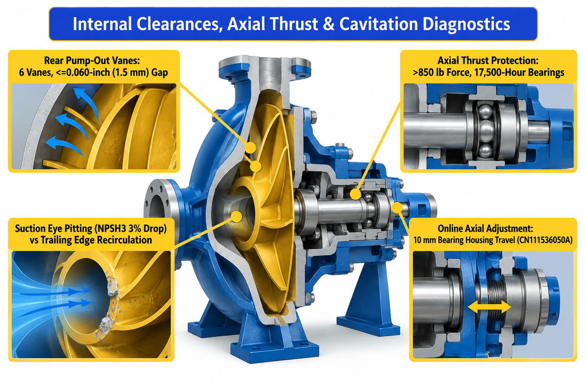
Even the best impeller design loses performance when internal running clearances open up or vapor cavitation attacks the blades. On a closed impeller, renewable casing and impeller wear rings restrict high-pressure volute liquid from leaking back to the suction eye. As radial wear-ring clearance doubles from its as-built design fit, internal recirculation increases and volumetric efficiency decreases.
The mechanical challenge facing semi-open impellers is axial thrust and front-to-back face clearance. Per Pumps & Systems, a medium ANSI pump develops over 850 pounds of axial force, with thrust bearings rated for 17,500 hours. To reduce stuffing-box pressure and axial thrust without drilling balance holes, designers cast radial pump-out vanes onto the rear shroud. Per Pumps & Systems, rear vanes reduce thrust, with an optimum of 6 vanes, and lose effectiveness above a 0.060-inch (1.5 mm) gap.
Maintenance engineers can determine the hydraulic root cause of pitting by looking at where it occurs on an impeller blade. Pitting concentrated at the suction eye leading edge indicates classic NPSH cavitation, where the first-stage head drops by 3% at the Hydraulic Institute NPSH3 threshold. Pitting on the high pressure side of a vane, or near the outer trailing edge, is an indication of low flow recirculation and excessive cutwater turbulence.
⚠️ Engineering Scope Limitation: Pump-Out Vanes & Balance Holes Under Suction Lift
Rear pump-out vanes and shroud balance holes reduce axial thrust and pressure in the mechanical-seal chamber. However, under suction lift, they may pull air across the seal or cause hot liquids near vapor pressure to flash. Heavy petrochemical standards do not endorse pump-out vanes for primary axial thrust balance.
| Manufacturer / Brand | Core Impeller Geometries Supplied | Primary Duty Focus & Testing Standards |
|---|---|---|
| BBP Manufacturing (bbpmfg.com) | Closed multistage, double-suction Francis-vane split-case, semi-open high-chrome slurry, and non-clog sewage rotors. | Two-plane dynamic rotor balancing and closed-loop hydraulic performance testing across industrial pump lines. |
| Sulzer / KSB | Closed process impellers, twisted Francis vanes, and channel sewage rotors. | Petrochemical refinery, power generation, and municipal water transport. |
| Xylem (Goulds / Flygt) | Semi-open process impellers and swept-back N-technology wastewater rotors. | Chemical processing and municipal non-clog submersible lift stations. |
| Weir Warman | Heavy-section closed and semi-open high-chrome white iron slurry impellers. | Mineral processing, mill discharge, and hydrocyclone feed duties. |
Can impeller blade clearance be adjusted in the field without replacing the impeller?
Yes, on semi-open and open impellers, technicians can adjust bearing housing jackscrews or shims externally to restore worn blade-to-casing clearance without opening the casing. Closed impellers cannot be axially shimmed to restore radial clearance and require replacing the worn casing or impeller wear rings.
For example, axial-adjustment semi-open pump designs such as Patent CN111536050A provide a 10mm axial travel slot on the bearing housing. Operators can reset the front vane gap externally as abrasive wear progresses.
Metallurgy, Cost Multipliers, and the 4-Gate Duty-to-Blade Selection Protocol
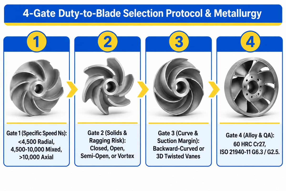
Matching impeller blade geometry to fluid mechanics is only half the specification. If the alloy cannot withstand the fluid’s chlorides, pH, or solid particle velocity, erosion-corrosion rapidly destroys the vane leading edges. For clean water, standard gray cast iron is the baseline. For more corrosive fluids, the alloys become more expensive and pricing is by alloy weight and foundry tooling (request a quote for custom castings). For severe mineral abrasion, per BBP Manufacturing’s foundry specifications, heavy slurry impellers use high-chrome white iron hardened to 60 HRC and tested to ISO 9906:2012 Grade 1U/2B.
All cast or trimmed impellers must also pass strict dynamic balance verification before installation. Per BBP’s static and dynamic pump impeller balancing guide, rotors use ISO 21940-11 G6.3 (6.3 mm/s), G2.5 (2.5 mm/s), or API 610 4W/N (6350W/N). Ordering OEM pre-balanced impellers avoids the high capital cost of an in-house balancing machine.
Before issuing a purchase requisition, run your duty parameters through our 4-Gate Duty-to-Blade Selection Protocol below. It locks in flow profile, shroud enclosure, vane curvature and metallurgy in that order.
| 4-Gate Duty-to-Blade Selection Protocol | Input Engineering Variable | Decision Thresholds | Resulting Impeller Specification |
|---|---|---|---|
| Gate 1: Specific Speed (Ns) | Design flow rate (Q), total head (H), and motor shaft speed | Ns < 4,500 US vs. 4,500–10,000 vs. > 10,000 (ANSI/HI 14.3) | Select Radial, Francis (60°–70°), Mixed-Flow (45° per ANSI/HI), or Axial profile. |
| Gate 2: Solids & Ragging Risk | Suspended solids concentration and fiber length | Clean water vs. stringy fibers vs. industrial slurry vs. heavy grit | Select Closed (highest clean-water efficiency), Open, Semi-Open (5 times wear area per Eng-Tips), or Vortex. |
| Gate 3: Curve & Suction Margin | NPSHa vs. NPSH3 (3% head drop per ANSI/HI) | Tight NPSH margin, two-phase gas, or diameter trim ≤ 15% (Empowering Pumps) | Specify backward-curved or 3D twisted vanes + splitter blades (45 to 55 percent radius per US8128360B2). |
| Gate 4: Alloy & QA Verification | Fluid pH, chlorides, abrasion, and rotor speed | Cast iron, stainless steel, duplex, or high-chrome white iron alloy | Mandate CNC-machined surface finish (Ra = 1.276 μm vs. rough sand-cast Ra = 81.72 μm per MDPI) and two-plane dynamic rotor balancing. |
Procurement RFQ Checklist for Custom & Replacement Pump Impellers
-
✔
Specify rated flow rate, total head, motor shaft speed, and liquid density referenced to 998.2 kg/m³ water at 20 °C above the 3% NPSH3 drop (ANSI/HI 14.1-14.2). -
✔
State shroud enclosure (closed, semi-open, open, or vortex), splitter blades at 45 to 55 percent radius (US8128360B2), and diameter trims within 15% with at least 8 mm tip thickness (Empowering Pumps). -
✔
Define closed wear-ring clearance or semi-open rear pump-out vane geometry (optimum 6 vanes, maximum 0.060 in. / 1.5 mm gap per Pumps & Systems). -
✔
Specify alloy grade—including high-chrome white iron alloy for abrasive slurries—and machined channel finish of Ra = 1.276 μm vs. rough sand-cast Ra = 81.72 μm (MDPI). -
✔
Require two-plane dynamic rotor balancing and closed-loop hydraulic test-stand verification referenced to water at 20 °C (68 °F) (ANSI/HI 14.1-14.2).
Frequently Asked Questions
Q: What are the different types of pump impellers and how are their blades classified?
Pump impellers are classified along three independent mechanical axes: shroud enclosure, vane curvature and specific-speed flow direction.
Structurally, rotors can be closed (double shrouds), semi-open (single back shroud), or open (hub-mounted vanes). By blade curvature, vanes can be backward-curved, radial-straight, forward-curved, or twisted in a 3D Francis configuration with a 60°-70° exit angle (ANSI/HI 14.1-14.2). By flow path, impellers operate as radial, mixed-flow (45°), axial propeller, or recessed vortex types.
Q: Which type of impeller is most efficient for industrial centrifugal pumps?
A closed radial impeller with backward-curved blades achieves the highest hydraulic efficiency in centrifugal pumps operating on clean water at 20 °C (ANSI/HI 14.1-14.2).
Its front and back shrouds help prevent tip spill across the casing, while radial wear rings restrict recirculation. Stepping down to the semi-open or open impeller, sacrifices peak clean water efficiency, but allows the passage of suspended solids and fibrous debris without clogging.
#
Q: What are the names of the main parts of a centrifugal pump impeller?
A centrifugal pump impeller is made up of six main structural elements, which include a central hub, suction eye, blades (vanes), back shroud, front shroud and wear ring surfaces.
The hub is threaded on to the drive shaft to transmit torque. Liquid enters axially through the low pressure suction eye and accelerates along the blades to the outer tip. The back shroud supports the vanes against axial thrust, while closed impellers add a front shroud and machined wear ring journals.
Q: Should all impeller blades on a pump rotor be the same size?
Standard impellers use identical blades, but high-head impellers often alternate main blades with shorter splitter blades starting at 45 to 55 percent radius (US8128360B2).
Q: How does fluid viscosity affect centrifugal impeller blade selection and efficiency?
Increased fluid viscosity causes higher frictional drag in the blade channels and outer shroud surfaces, which increases the power consumed by the motor and reduces the flow and head.
For clean liquids with properties close to those of water at 20 °C and a reference density of 998.2 kg/m³ (ANSI/HI 14.1-14.2), closed backward-curved impellers offer peak hydraulic efficiency. As viscosity and suspended solids rise, closed passages experience increased skin friction and clogging. Engineers switch to open impellers or semi-open impellers with wider vane clearances, or opt for helicoidal screw-centrifugal rotors. For highly viscous pastes outside the centrifugal limits, plants resort to positive-displacement pumps, and open-tank Rushton radial or pitched-blade agitators.
Q: How often should a pump impeller be dynamically balanced during maintenance?
Each new, lathe-trimmed, or weld-repaired pump impeller must undergo two-plane dynamic rotor balancing before assembly.
When metal is removed by diameter trimming (within the 15% maximum reduction limit per Empowering Pumps) or trailing-edge underfiling, balancing prevents radial vibration and protects thrust bearings rated for 17,500 hours (Pumps & Systems).
About This Hydraulic & Foundry Analysis
This guide was prepared by CYH, a member of the rotating equipment engineering team at BBP Manufacturing Co. Ltd. This guide combines the Hydraulic Institute ANSI/HI 14.1-14.2 and 14.3 specific-speed rules, 2025 impeller surface roughness benchmarks and BBP Manufacturing’s closed loop hydraulic test stand engineering practices for multistage, split case pumps, and high-chrome white-iron slurry pumps.
Need Custom-Cast or Precision-Balanced Impellers for Your Pump Duty.
Quote your flow rate, total head, NPSH available, solids concentration and fluid chemistry to BBP Manufacturing’s hydraulic engineering team. We will assess closed, semi-open, double-suction and high-chrome slurry pump configurations and provide options best suited to your plant.
References & Sources
- ANSI/HI 14.1-14.2 Pump Data Tool Table of Definitions Hydraulic Institute
- Rotodynamic & Centrifugal Pump Standards FAQs (ANSI/HI 14.3) Hydraulic Institute
- Publication WI001 / CIR832: Centrifugal Pump Selection, Specific Speed, and Affinity Laws University of Florida IFAS Extension
- Performance Comparison of Cast Iron vs. Composite Centrifugal Pump Impellers (Machines 2025, 13(8), 729) MDPI
- Experimental Study on 2D Cylindrical and 3D Twisted Blades in Centrifugal Pumps (2025) International Journal of Heat and Fluid Flow
- US8128360B2: Impeller with Primary and Splitter Blades for Centrifugal Pumps USPTO (Google Patents)
- CN111536050A: Semi-Open Impeller Centrifugal Pump with Online Axial Adjustment CNIPA (Google Patents)
- Considerations for Impeller Trimming and Vane Underfiling (Heinz Bloch, P.E.) Empowering Pumps
- Why Are There Holes in My New Impeller? Part 3: Pump-Out Vanes Pumps & Systems Magazine
- Engineering Thread: Shroudless vs. Shrouded Impeller Wear Mechanics Eng-Tips Engineering Forums