Get in Touch with BBP

Quick Specs
| Body materials | ASTM A105 (forged steel), A216 WCB (cast steel) |
| Pressure classes | ANSI Class 150 to 2500 |
| Line sizes | 1 in to 20 in (25 mm to 500 mm) |
| Minimum-flow setpoint range | No single percentage applies across pump classes; e.g. 25% of BEP for BBP boiler feed pumps, consult the certified curve for other classes (see below) |
| Functions in one body | 3: check valve, bypass flow control, cavitation-suppressing pressure management |
An automatic recirculation valve is a self-actuated device that protects a centrifugal pump from damage by keeping flow through the pump above a minimum safe level, without any external power or control signal. On boiler feed and other high-pressure pumps, this single valve replaces what would otherwise be a check valve, a flow-metering loop, and a control valve wired into a PLC. For a feedwater package serving industrial steam boilers from Taiguo, agree the operating pressure, steam-load range and pump minimum-flow requirement with the relevant equipment suppliers before selecting the bypass arrangement.
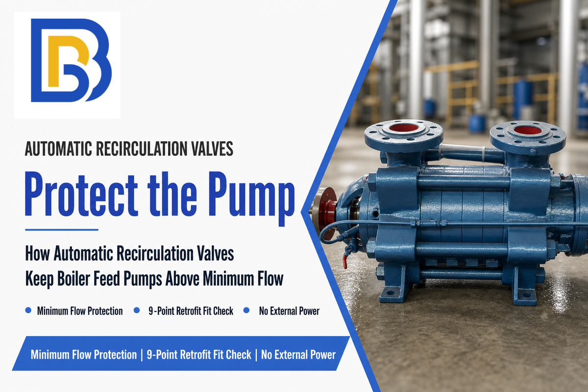
An automatic recirculation valve (ARC valve) combines a check valve, a flow-sensing bypass element, and a cavitation-suppressing pressure stage in one body to keep a centrifugal pump above its minimum safe flow. It opens a bypass path back to the suction source automatically whenever process demand drops below the pump’s rated minimum, then closes as demand returns. No external power, DCS signal, or instrument air is required.
In This Article
- Why boiler feed and high-pressure pumps fail below their minimum flow, with real failure cases
- How the three functions actually work inside the valve body, and why not every design uses the same pressure-management approach
- A cost-driver framework for comparing an ARC valve against a separate bypass loop, without inventing a fake dollar total
- A 9-point retrofit fit-check before you specify one for an existing pump skid
- When an ARC valve won’t solve your problem, and how it differs from a fire pump’s circulation relief valve
What Is an Automatic Recirculation Valve?
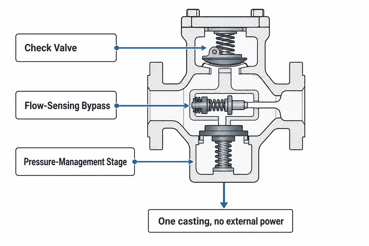
An automatic recirculation valve is a mechanically self-actuated device that combines a check valve, a flow-sensing bypass element, and a pressure-management stage in a single body to keep a centrifugal pump above its minimum safe flow. Field engineers and manufacturers alike describe the same core design across independent sources: a flow-sensitive disc or main valve element that senses forward flow, and a linked bypass element that opens in inverse proportion as forward flow drops.
Specifying an automatic recirculation valve for pump protection earns a reputation for reliable service because there’s no external control loop to fail. That same mechanical logic opens the bypass and closes it once flow returns to the required minimum flow, replacing what would otherwise need a manual bypass valve and an operator watching a gauge.
Buyers often assume this is just a check valve with a bypass line bolted on, and ask why they can’t build the same protection from a plain check valve plus a separately specified minimum-flow control valve skid. Footprint and point count answer the question: a control-valve skid needs its own flow meter, pressure transmitters, and a small PLC or DCS loop to modulate the bypass, while the ARC valve does the same job with pilots and springs inside one casting. A petroleum engineer on Eng-Tips put the distinction plainly: control valves suit plant-based control where flow is well known and stable, while ARC valves suit facility-based protection where flow is variable or unknown, exactly the case on a boiler feed pump.
This three-in-one design earns its keep on high-differential-pressure services: a control valve that fails to open in time across 1,000 psig differential can leave a stalled pump churning into heat damage within minutes, while the ARC valve’s mechanical linkage starts throttling the main path and opening the bypass in proportion the moment forward flow drops, with no signal path to fail.
Why Boiler Feed and High-Pressure Pumps Fail Without Minimum-Flow Protection
A centrifugal pump running below its minimum continuous flow suffers internal recirculation at the impeller inlet and discharge, and the mechanical energy that isn’t converted into useful head is dissipated as heat directly into the pumped fluid. As that fluid heats, its vapor pressure climbs until cavitation begins, eroding the impeller and casing while thrust and vibration loads climb toward bearing and seal failure.
Warren H. Fraser, Chief Hydraulic Engineer at Worthington Pump and an ASME Centrifugal Pump Performance Test Code committee member, documented two real failures from operating in the recirculation zone: a double-suction cooling-tower pump run at 75% of BEP had its cast-iron impeller vanes cavitate to the point of breaking off within a few weeks, and a high-pressure boiler feed pump with a specific speed of 1,500 that idled at low load during plant startup suffered fatigue failure of its diffuser vanes from cyclic loading in the discharge-recirculation zone.
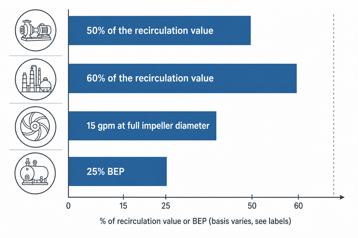
| Pump class | Continuous minimum flow | Source |
|---|---|---|
| Small pump, ≤2,500 GPM / ≤150 ft head | 50% of the recirculation value (25% intermittent) | Fraser, Worthington Pump |
| Any size, hydrocarbon service | 60% of the recirculation value (25% intermittent) | Fraser, Worthington Pump |
| ANSI AA (1×1.5-6), max impeller | 15 gpm at full impeller diameter | Jim Elsey, Pumps & Systems |
| BBP multistage boiler feed pump line | Internal recirculation and overheating below 25% BEP | BBP product specification |
BBP’s own multistage boiler feed pump line documents this directly: running one of its BFPs below 25% of best efficiency point drives internal recirculation and overheating inside the pump, which is why BBP specifies an automatic minimum-flow recirculating loop back to the deaerator for that duty. The underlying physics matters too: feed water leaves the deaerator already near its saturation temperature, so even the modest heat rise from running below minimum flow is enough to push it toward vapor pressure. Deaerator feedwater systems are typically installed with the deaerator elevated well above the pump to provide static head margin against exactly this risk; without that elevation, the NPSH margin at the pump’s first-stage suction eye would leave little thermal cushion if recirculation raises fluid temperature further. BBP tracks that specification against its own installed base: a 150 MW coal-fired utility running two BBP BB5 boiler feed pumps in a 2×100% configuration logged 97.8% availability over a 24-month observation period with the minimum-flow loop in continuous service, and a separate biomass cogeneration retrofit across Brazil and Eastern Europe went 18 months with zero seal-related downtime after a DLC seal upgrade paired with the same minimum-flow protection.
Buyers sometimes push back that their pump has run for years without a dedicated recirculation valve, so the risk must be overstated. That argument mistakes absence of a documented failure for absence of accumulated wear: bearing life and seal life degrade with every hour spent below minimum flow long before a catastrophic failure shows up on a maintenance log, and the manufacturer’s certified minimum-flow curve is the baseline any warranty claim or field-failure investigation will be measured against. A single deferred maintenance event is a far cheaper lesson than the vane damage Fraser documented.
Higher-speed boiler feed pumps make the problem worse: a stage spinning at 3,600 RPM converts a given flow deficit into heat faster than the same stage at 1,800 RPM, which is one reason multistage BFW pumps show recirculation damage sooner than slow, low-head process pumps. On the horizontal end-suction chemical process pumps it covers, ANSI B73.1 sets a standard L10 bearing-life design target of 17,500 hours at the rated operating point, illustrating how aggressively rated bearing life is calculated industry-wide, a target class that erodes on any pump spending extended periods below its minimum continuous flow. On the multistage boiler feed side specifically, API 610 assumes a centrifugal pump in continuous refinery service can run 3 years between planned shutdowns, a bar it cannot clear if part of that period is spent starved of flow. In feed water service, where fluid temperatures commonly run from about 100°C to over 200°C depending on plant pressure, water’s vapor pressure climbs steeply with temperature, so even a modest temperature increase inside a starved casing is enough to trigger cavitation well before the fluid reaches a visibly abnormal pressure reading.
Vibration and thrust load don’t increase in a straight line with falling flow. Once demand exceeds a pump’s turndown capability, the resulting instability tends to show up first as bearing and diffuser wear, the failure pattern Fraser documented, rather than as an abrupt shutdown. A recirculation loop sized correctly reduces that thrust load back toward its rated range as soon as the bypass opens.
How an ARC Valve Works, the Core Mechanism
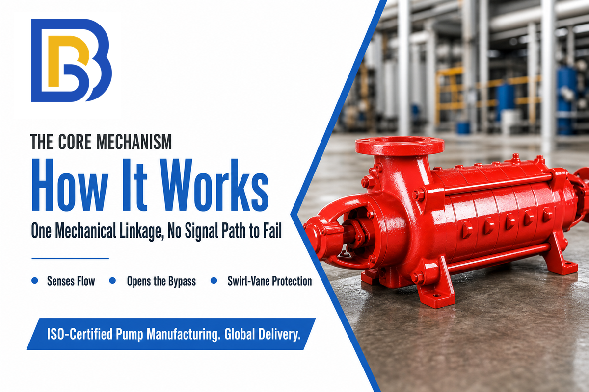
The automatic recirculation valve working principle starts inside the body, where a main valve element senses flow between inlet and outlet and links to a bypass element through a shared stem. As forward flow falls, the main element moves toward its seat and lifts the bypass element, opening a path back to suction; as flow recovers, the bypass closes again. When fully seated, it also functions as a check valve, blocking reverse flow into the pump on shutdown.
Readers looking for an automatic recirculation valve diagram can consult the patent’s own drawing set (FIG. 1 through FIG. 3), which shows the swirl vanes positioned at the bypass adapter outlet.
The valve is connected directly into the pump discharge main line, ahead of any check valve the plant may already have, and its bypass circuit routes low-flow fluid back to a suction tank, deaerator, or condenser rather than to drain. The bypass automatically opens whenever forward flow drops below the setpoint, and the same linkage closes the bypass again once flow recovers. No control system, back pressure transmitter, or operator input is required, and that absence of external logic is what lets the valve extend service intervals without a recalibration schedule.
| Function | Trigger condition | What it prevents |
|---|---|---|
| Flow sensing | Continuous, via main element position | Blind operation with no feedback on actual pump duty |
| Bypass modulation | Forward flow drops below the setpoint | Overheating and cavitation at low or zero net flow |
| Check function | Main element fully seated (pump stopped) | Reverse rotation and backflow into the pump casing |
Where designs genuinely diverge is the cavitation-suppression stage on the bypass side. Some manufacturers publish a multi-stage or multi-orifice trim that breaks a large pressure drop into a series of smaller recoveries so no single stage falls below the fluid’s vapor pressure. Granted Canadian patent CA2211146C (Pentair, originally filed by Tyco Flow Control) takes a different route: it protects the downstream piping with a bypass adapter fitted with helical swirl vanes that impart a rapid rotating motion to the bypass fluid, preventing cavitation bubbles from imploding directly against the pipe wall rather than staging the pressure drop at all. Both approaches solve the same problem, protecting the bypass line from erosion at high differential pressure, with different internal geometry, so a buyer comparing two ARC valves on a datasheet shouldn’t assume “multi-stage” is the only legitimate design.
ARC Valve vs. a Separate Minimum-Flow Bypass Loop, Cost Driver Framework
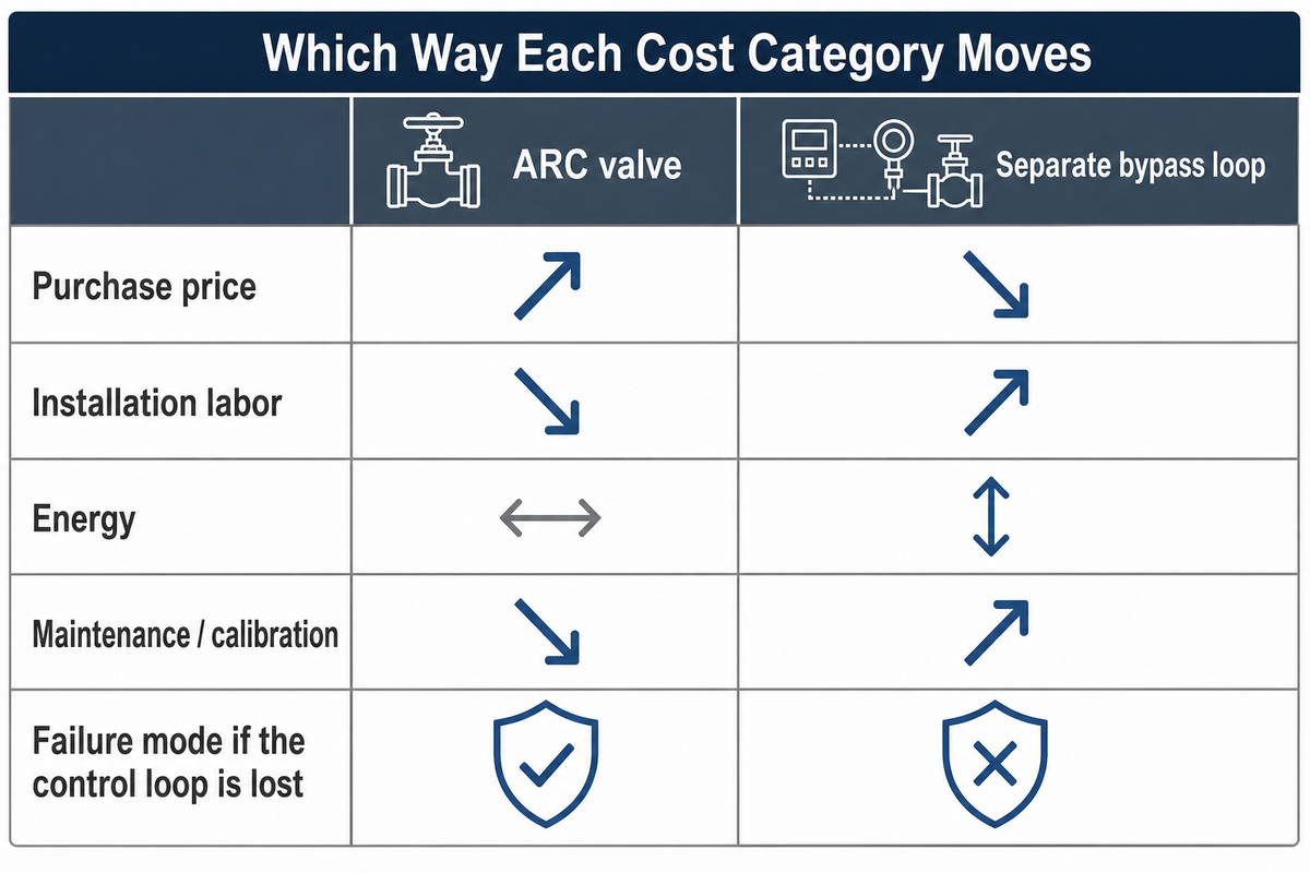
Buyers searching for an automatic recirculation valve price expect a single number, but choosing between an all-in-one ARC valve and assembling a check valve, flow element, and control valve into your own bypass loop isn’t a question with a single dollar answer, because lifecycle cost depends on installation-specific operating cycles, energy pricing, and maintenance history that no generic comparison can supply. What a buyer can compare honestly is which cost categories move, and in which direction, when the parts count drops from three instrumented components to one self-actuated valve.
Cost-driver framework — which way each category moves with an ARC valve vs. a separate bypass loop:
| Cost category | ARC valve | Separate bypass loop |
|---|---|---|
| Purchase price | Higher per unit (specialty body and trim) | Lower per component, but three components |
| Installation labor | One valve, one set of connections | Flow meter, transmitters, PLC wiring, and commissioning |
| Energy (per U.S. DOE lifecycle-cost accounting) | Bypass opens only when needed | Depends entirely on control-loop tuning |
| Maintenance / calibration | Trim inspection on a multi-year interval | Periodic flow-meter and transmitter calibration |
| Failure mode if the control loop is lost | None — mechanically self-actuated | Pump unprotected until the loop is restored |
The Hydraulic Institute’s own worked lifecycle-cost example puts the scale in perspective: a 100-hp pump with a $30,000 installed cost running continuously at $0.08 per kWh accrues roughly $52,000 in electricity cost per year and about $780,000 over 15 years; installed cost is only about 4% of lifetime energy cost on a continuously running pump. Against numbers that size, the price delta between an ARC valve and a bare check valve is a rounding error; the categories that actually move are engineering hours, instrumentation maintenance, and the single-point-of-failure risk in the control loop.
One caveat matters here: the numbers above describe a continuously running, high-differential pump, not every installation. DOE, Hydraulic Institute, and Europump’s own joint guide on variable-speed pumping documents a San Francisco refinery, running a 1,650 kW primary feed pump among others, where pumps running as low as 40% of best efficiency point were failing seals and bearings roughly once a year, and notes that even at maximum flow a control valve is normally left 10% shut for control purposes, wasting energy on every cycle regardless of how the minimum-flow protection is engineered. Low-differential, low-duty-cycle pumps won’t show the same payback as a high-pressure boiler feed pump running continuously. Don’t accept a vendor’s generic 5-year total without your own operating hours and energy tariff behind it.
None of that makes the all-in-one valve inherently more economical on every project; on a low-duty-cycle pump, the added purchase cost may simply be costly overhead. On continuously running boiler feed service, though, the downtime avoided by eliminating a single point of failure in the control loop works in the ARC valve’s favor over the pump’s service life, and correctly sized trim helps decrease unplanned maintenance visits along the way; run the comparison with your own downtime cost and maintenance history rather than assuming a fixed payback period.
Sizing and Retrofit Compatibility, What to Check Before Specifying One
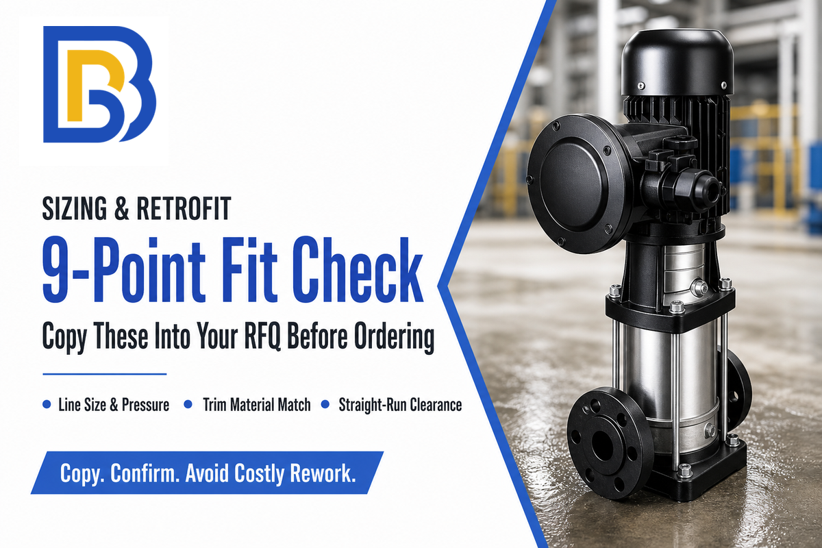
Retrofitting an ARC valve onto an existing pump skid fails most often not because the valve is wrong, but because someone skipped a parameter that only shows up once the valve is on site and the line doesn’t match. A single mismatch, a 150 mm line spec’d against a 100 mm existing flange, or a trim rated to 1,500 psi installed on a service that peaks at 2,200 psi, is enough to send the whole skid back to the shop. Nine checks below cover the parameters that actually block an installation, not generic “consult the manufacturer” advice. When a project includes separately machined valve bodies or flanged components, custom valve-body machining from Zhenling is a component-level sourcing reference; valve sizing, pressure qualification and final assembly acceptance remain with the responsible valve supplier and project engineer.
The 9-Point Retrofit Fit Check
Retrofit fit-check — copy these into your RFQ before ordering:
| Parameter | Recommended range | Why it matters | How to verify |
|---|---|---|---|
| Line size | Match existing discharge line, 1″-20″ | Mismatch forces a re-pipe | Field-measure the flange bore |
| Inlet/outlet pressure | Full range across pump curve | Sets the pressure class needed | Pump vendor’s certified curve |
| Minimum continuous flow rate | From pump curve, not a generic percentage | Sets the bypass trip point | Pump vendor’s certified curve |
| Orifice Cv at max spillback | Sized to the maximum spillback flow | Undersized trim erodes prematurely | ISA-75.01.01 liquid sizing calc |
| Body pressure class | ANSI 150-2500 | Under-rated body cannot be field-upgraded | Match to ASME B16.34 rating table |
| Trim material | Match to actual water chemistry, not a generic menu | Wrong alloy shortens trim life | Water analysis: pH, dissolved oxygen, chlorides |
| Straight-run clearance | Per manufacturer’s installation drawing | Insufficient clearance disturbs flow sensing | Site walk-down against the drawing |
| Control-signal type | None required (self-actuated) | Confirms no DCS point needs to be freed up | Confirm with I&C before removing an old loop |
| Installation orientation | Per manufacturer’s flow-arrow marking | Reversed installation defeats the check function | Verify arrow against as-built P&ID |
Skipping any of the nine checks can let low flow conditions reach the pump before the recirculation flow compensates, and the gap tends to surface as a symptom during commissioning rather than as a line on a datasheet. A retrofit that assumes a generic percentage instead of consulting the pump’s own minimum flow required can leave the main flow undersized for real flow demand at partial load, and a valve trimmed to the wrong pre-determined minimum flow setpoint won’t deliver the centrifugal pump protection the certified curve assumes. Sites that maintain a documented commissioning checklist tend to catch this kind of mismatch before it causes damage, unlike sites that skip it; in the severe cases where a mismatch goes unnoticed for months, the impeller can end up permanently damaged before the next scheduled inspection.
Once the valve is commissioned, the protection path itself deserves a periodic check, not just the pump. The U.S. Nuclear Regulatory Commission’s Bulletin 86-03 documented four real cases where a design deficiency in an air-operated isolation valve on a minimum-flow recirculation line could remove protection for multiple emergency pumps at once, a scenario the bulletin warned would leave the pumps deadheaded and damaged within minutes if it occurred, and it gave affected plants 30 days to report the vulnerability and 90 days to submit a long-term fix schedule. That bulletin covers nuclear safety systems specifically, but the underlying lesson generalizes to any minimum-flow protection scheme with an isolation valve upstream or downstream of the ARC valve for maintenance: verify that valve’s position and function on the same interval you test the pump, not just at initial commissioning.
Who Makes Automatic Recirculation Valves
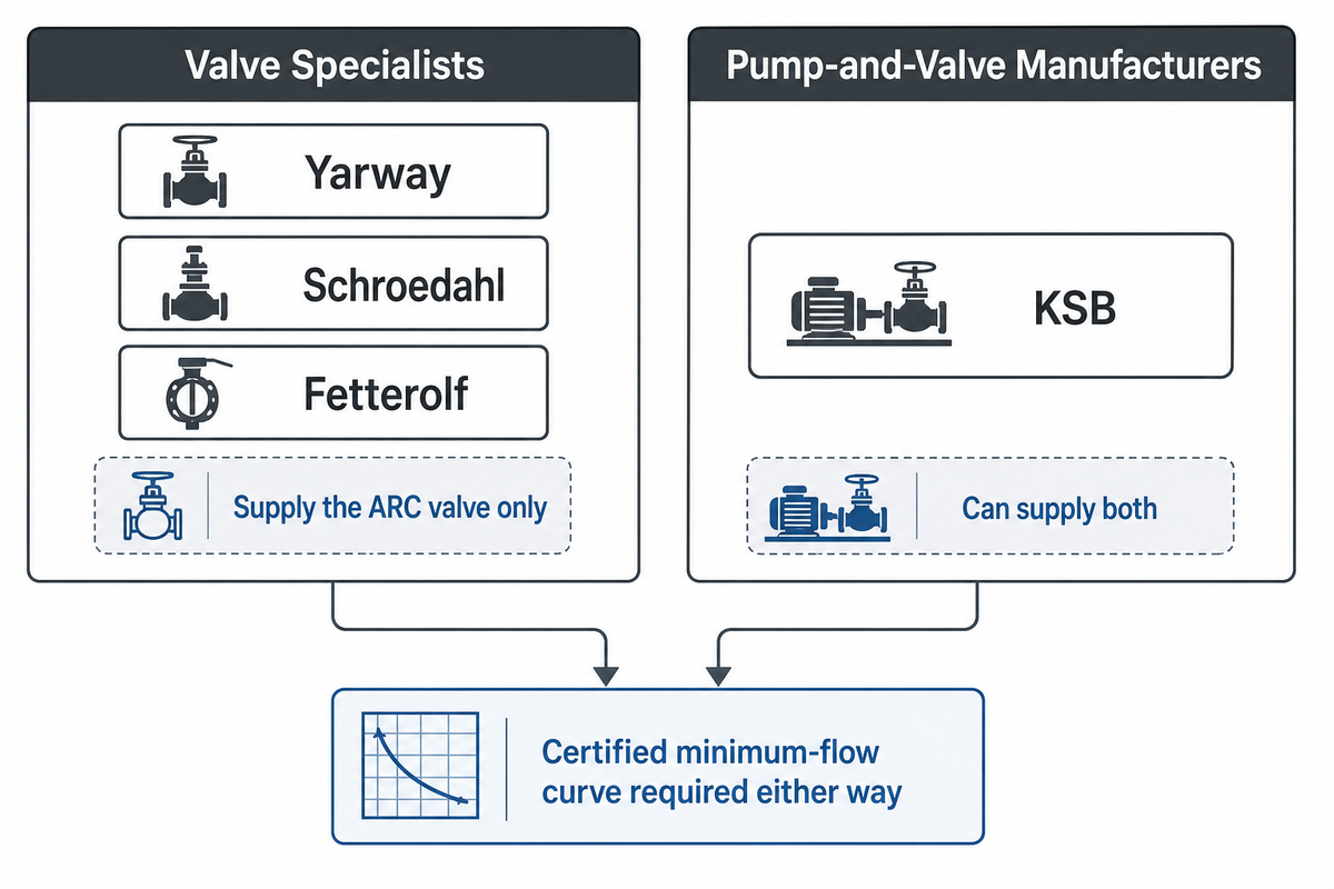
Buyers researching automatic recirculation valve manufacturers will see the same handful of specialty names on boiler feed pump RFQs for decades running: Yarway, Schroedahl, Schroeder Valves, and Fetterolf, alongside larger pump-and-valve manufacturers like KSB that can supply both the pump and its protection valve. Most of the specialist names don’t build the pump itself, which is why the two purchasing decisions are usually made separately unless a single vendor is supplying both.
Any of them can supply a valve sized for a boiler feedwater pump once the pump vendor’s certified minimum-flow curve is in hand. Trim life on a correctly sized valve in continuous boiler feed service depends on water chemistry and differential pressure, so ask the valve vendor for a rebuild-interval estimate against your own operating conditions rather than a generic figure.
BBP doesn’t sell ARC valves; its multistage and high-pressure boiler feed pump lines are exactly the equipment these valves protect, and BBP’s own boiler feed pump series publishes a certified minimum-flow curve and specifies an automatic minimum-flow recirculating loop for that duty point. Buyers sizing a new pump and valve together can use BBP’s BBP model selector to get the certified minimum-flow figure an ARC valve vendor will need before quoting a trim.
Conditions That Make an ARC Valve the Wrong Fix
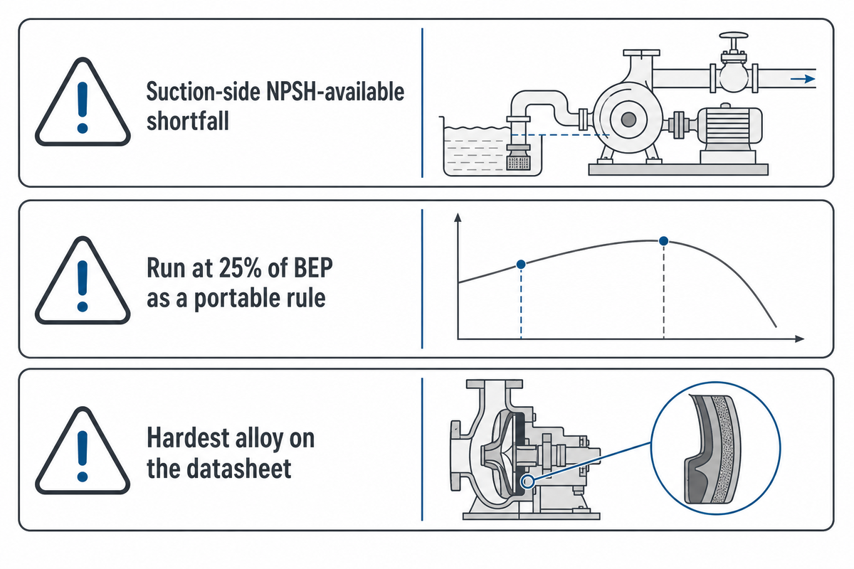
An automatic recirculation valve solves one specific problem, sustaining flow above the pump’s minimum on the discharge side, and buyers occasionally specify one to fix a completely different problem it can’t touch. Three documented boundary conditions are worth checking before ordering.
“NPSHA should always exceed NPSHR, and the difference between these values is known as the NPSH margin.”
First, an ARC valve can’t fix a suction-side NPSH-available shortfall. It protects a pump that has enough NPSH available but is running too low on flow; if the suction system itself can’t supply enough head above vapor pressure, adding a recirculation valve on the discharge side does nothing to the suction condition causing cavitation. Second, don’t treat “run at 25% of BEP” as a portable rule: that number reflects one specific pump family’s design and internal recirculation tolerance, and independent field guidance explicitly warns against a universal minimum-flow percentage because the governing limit changes with suction specific speed, impeller geometry, and service. Third, trim material selection isn’t a hardness contest: options range from cobalt-based hardfacing alloys like Stellite 6, roughly 28% chromium and 4% tungsten in a cobalt matrix, to precipitation-hardened stainless grades like 17-4 PH, and in aggressive or oxygen-scavenged boiler feedwater the hardest alloy on the datasheet is not automatically the right default. Trim should be matched to the actual measured water chemistry, a decision best made with the valve vendor rather than by defaulting to maximum hardness.
Automatic Recirculation Valve vs. Fire Pump Circulation Relief Valve, Don’t Confuse These Two Devices
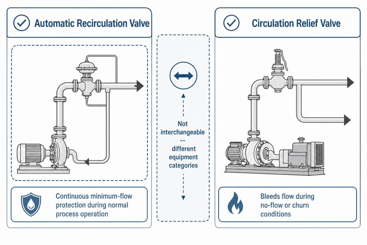
A field crew that has only worked fire protection systems will sometimes hear “recirculation valve” and reach for the wrong part number, because fire pump installations use a device with an overlapping name that solves a narrower problem. Municipal fire code guidance shows exactly how narrowly the circulation relief valve is defined within a fire pump system: a City of Miami high-rise fire pump guideline lists item 13 as the pressure relief valve, item 14 as the pressure reducing valve, and item 15 as the circulation relief valve, citing NFPA 20 (2016 edition) Section 4.11 for the latter, three separately numbered components in a materials list that has no line item for an ARC valve at all, because ARC valves belong to a different equipment category entirely. Fire pumps use a circulation relief valve to bleed a small continuous flow whenever the pump runs at no-flow or churn conditions, whether during periodic churn testing or an actual fire event with no hose demand, so the pump doesn’t overheat. NFPA 20 Section 14.2.6.2.3 commissions fire pumps at three flow points, 0%, 100%, and 150% of rated flow, a narrower duty than an ARC valve’s continuous minimum-flow protection during normal process operation.
| Failure Type / Symptom | Likely cause | Verification step |
|---|---|---|
| Bypass stays open at design flow | Check disc not sealing, seat erosion | Inspect seat, measure leakage class |
| High-frequency noise in bypass line | Cavitation in a single pressure stage | Acoustic survey, stage-pressure check |
| Visible pitting or corrosion on trim surfaces at a scheduled rebuild | Trim alloy mismatched to actual water chemistry | Compare trim alloy certification against water analysis: pH, dissolved oxygen, chlorides |
| Valve body or bonnet leak | Gasket failure, bolt relaxation from thermal cycling | Bubble test, visual bolting inspection |
| Erratic disc motion | Suction pulsation, or pump below minimum flow | Suction pressure trace against pump curve |
| No bypass flow at low load | Disc stuck closed, blocked bypass port | Clean and cycle-test the bypass path |
| Rapid trim wear, <2-year service life | Under-staged pressure drop for the differential | Inspect first-stage orifice for wire-drawn wear pattern |
| Two parallel valves both failing early | Both undersized for the same duty point (common design error) | Recheck both valves’ minimum-flow rating against the certified pump curve |
| Loud water-hammer on bypass closure | Disc closes too abruptly, no cushioning at the seat | Inspect closure damping against the manufacturer’s spec |
Confusing the two devices in a spec package is more than a naming slip: a circulation relief valve sized for a brief churn test won’t survive continuous minimum-flow duty on a boiler feed pump, and an ARC valve isn’t what an authority having jurisdiction expects to see on a fire pump submittal’s circulation-relief-valve line item; check the jurisdiction’s adopted NFPA 20 edition for the current section number. For NFPA 20-specific inspection detail on the fire-pump side of this distinction, see BBP’s split-case fire pump red-tag inspection guide.
Frequently Asked Questions
Q: What is an automatic recirculation valve?
An automatic recirculation valve is a self-actuated device combining a check valve, bypass control, and pressure management to protect a centrifugal pump from low-flow damage.
It senses forward flow through the pump and opens a bypass path back to the suction source whenever that flow drops below the pump’s minimum safe level, closing again as demand returns, all without external power, DCS input, or instrument air. The same body also functions as a check valve once the main element is fully seated, so a plant gets pump protection, bypass control, and reverse-flow blocking from a single casting instead of three separately specified components on the discharge line.
Q: What is the purpose of a recirculation valve?
An automatic recirculation valve’s purpose is to prevent cavitation, overheating, and thrust-bearing damage by maintaining minimum flow through the pump even when downstream demand drops well below normal operating levels.
It bleeds enough flow back to suction to keep the pump from overheating whenever downstream demand runs too low. Without that bypass path, the pumped fluid trapped inside a starved casing absorbs the pump’s mechanical energy as heat instead of useful head, its vapor pressure climbs, and cavitation erosion begins at the impeller and casing walls well before an operator would notice anything unusual on a discharge gauge.
Q: How does an automatic recirculation valve (ARV) work?
A flow-sensing main element moves in response to forward flow and mechanically opens a linked bypass element as that flow drops below the pump’s rated setpoint.
The bypass closes again as forward flow recovers, and when the main element is fully seated it also acts as a check valve, preventing reverse flow into the pump. Where designs genuinely differ is the cavitation-suppression stage on the bypass side: some manufacturers stage the pressure drop across several smaller orifices, while granted patent CA2211146C instead fits the bypass adapter with helical swirl vanes that impart a rotating motion to the fluid, protecting the downstream pipe wall without a multi-stage trim at all. Neither approach is universal, so a buyer comparing two datasheets should check which mechanism is actually inside the body before assuming they are interchangeable.
Q: What is the difference between an ARC valve and a minimum-flow control valve?
An ARC valve is self-actuated with no external power; a minimum-flow control valve needs a flow meter, pressure transmitters, and a control loop to modulate.
Control-valve routing is more finely adjustable but depends on that loop staying functional; ARC valves trade that adjustability for a linkage that cannot lose signal.
Q: Do automatic recirculation valves need external power?
No. An ARC valve operates mechanically through pilots and springs, with no electrical supply, instrument air, or control signal required to sense flow or move the bypass.
This is one of its main advantages over a control-valve-based bypass loop, which needs a flow meter, pressure transmitters, and a PLC or DCS loop to function, and risks losing protection if that loop goes offline, depending on the actuator’s fail-safe configuration. That difference matters most during a plant power interruption or a DCS fault: a control-valve loop can lose its position command at exactly the moment the pump most needs protection, while the ARC valve’s spring-and-pilot linkage keeps sensing flow and modulating the bypass regardless of what the control system is doing elsewhere on site.
Why We Write This
BBP manufactures the multistage and high-pressure boiler feed pumps that automatic recirculation valves are built to protect, so we track the minimum-flow specifications and failure modes across pump classes as part of certifying our own product line’s minimum-flow curves. This guide reflects that certification work, cross-checked against Hydraulic Institute standards and documented field failure cases, not a valve vendor’s marketing claim.
Reviewed by the BBP Manufacturing technical team.
References & Sources
- Flow Recirculation in Centrifugal Pumps — Warren H. Fraser, Worthington Pump / Texas A&M Turbomachinery Symposium
- Minimum Flow Redux — Jim Elsey, Pumps & Systems
- Understanding the 2024 Updates to ANSI/HI 9.6.1 — Hydraulic Institute
- Pump Lifecycle Cost FAQ — Hydraulic Institute
- Variable Speed Pumping: A Guide to Successful Applications — U.S. Department of Energy
- High-rise Fire Pump Guidelines — City of Miami Fire-Rescue
- Bulletin 86-03: Potential Failure of Multiple ECCS Pumps — U.S. Nuclear Regulatory Commission
- CA2211146C, Improved Automatic Recirculation Valve — Pentair Valves and Controls (Google Patents)
Related Articles
- Pump Cavitation Guide — the NPSH math and diagnostic sequence behind the failure modes described above
- Split Case Fire Pump NFPA 20 Red-Tag Inspection — how the fire-pump circulation relief valve is tested and inspected
- How to Write an RFQ for Industrial Pumps — the full specification checklist this article’s retrofit table is drawn from
- High-Pressure Multistage Pumps — BBP’s product line for the high-differential-pressure services this article covers