Get in Touch with BBP

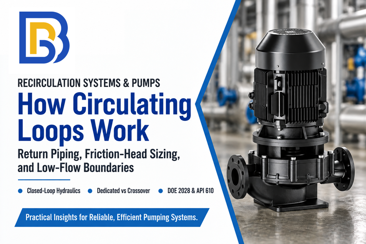
Recirculation involves routing a stream back through a closed loop. The fluid passes through a heat source or pump stage again instead of going to waste. A hot water recirculation loop in a domestic plumbing system is used to keep hot water between a water heater and a distant plumbing fixture. Such loops reduce the need to wait for hot water to be delivered. An on-demand system also has to circulate water through the system to make hot water available to a fixture. Delays may still occur due to long branch fixtures. Industrial plants use pump recirculation lines to protect high-head centrifugal pumps from thermal overload and cavitation at low-flow conditions.
Because of the wide scope of the term (plumbing, HVAC, automotive climate control and heavy process engineering) buyers often get contradictory definitions. A residential plumber using the term recirculation line refers to the return line to a distant plumbing fixture, like a shower or laundry. According to WARE for a steam-generating plant, the recirculation line on the boiler feedwater pump routes a small flow of water to the deaerator to prevent water from flashing to steam under low-load conditions. A rotating equipment specialist uses the same term to refer to reverse-flow vortices in the eye of a centrifugal impeller.
We examine closed-loop hydraulics, dedicated return lines versus crossover valves, pipe sizing, and copper velocity limits. We also cover the U.S. Department of Energy (DOE) May 22, 2028 circulator efficiency mandate and internal impeller cavitation remedies.
What Recirculation Means Across Plumbing, HVAC, and Industrial Pump Loops
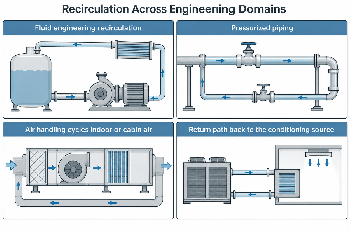
According to Merriam-Webster, recirculation means to circulate a fluid or gas again. In the field of engineering, when we talk about circulation of fluid or gas, we consider the thermodynamics, the type of fluid and the balance of pressure in the whole circuit. Usually in engineering practice, we use a one way open path to take the fluid from the supply point and discharge it to the drain. A recirculation system, on the other hand, creates a return path back to the conditioning source.
What Does Recirculation Mean Across Fluid Engineering vs Air Handling?
Fluid engineering recirculation moves liquid through pressurized piping to hold temperature or minimum pump flow, whereas air handling cycles indoor or cabin air across a coil. In both cases, the systems reuse conditioned media instead of treating raw incoming media. However, their mechanical components and their failure risks are different.
On vehicle or building air conditioning system, by pressing the recirculation button, the damper to the intake side is closed to block outside air. In a car, this control is often labeled as the recirc button. When you activate recirculation mode, the blower stops pulling hot air from outside into the cabin. Recirculation reduces the intake of road exhaust fumes, but pollutants can still enter through leakage or ventilation. The blower pulls conditioned air from passenger cabin across the evaporator coil. This action helps cool the air and cool the car faster while reducing load on the compressor.
Keeping air inside running reduces outdoor air dust and smoke, but drivers do switch back to Fresh Air or defroster during the cold winter months. Otherwise, exhaled moisture will condense and fog the windshield when cold air hits the glass. Drivers weigh cooled air reuse against air from outside (or air from the outside). That fresh intake balances fog and carbon dioxide build-up while keeping air in the car heated or cooled with steady airflow and air movement inside the car or inside your car.
Closed loops of liquids have to obey more strict hydraulic laws. Liquid recirculation requires a flow path provided by a return pipe line and a pressure difference provided by a pump. In a forced circulation system, the pump is a pump. In a thermosiphon system, the flow path is provided by density differences. For a hot-water recirculating system equipped with a check valve and temperature controls, the check valves limit reverse flow and the temperature controls govern circulation and Heat transfer. The temperature controls also govern Heat transfer in the system. According to Research and Markets, in January 2024, Atlas Copco acquired Kracht GmbH to expand its industrial pump portfolio.
| Recirculation System Type & Category | Primary Engineering Purpose | Core Hardware Involved | Typical Flow & Operating Trigger |
|---|---|---|---|
| External Distribution Loop Recirculation (DHW Plumbing & Hydronic HVAC Type) | Keep hot or chilled water moving through distribution piping so distant fixtures or coils receive conditioned water immediately. | Wet-rotor or dry-rotor recirculation pump, insulated return pipe or crossover valve, spring check valve, aquastat sensor. | Domestic hot-water return flow offsets distribution heat loss; hydronic HVAC flow carries the heating or cooling load at the design temperature difference. Pump head covers the circuit’s hydraulic losses. |
| Thermal Crossover Valve DHW Retrofit (2-Pipe Type) | Route cooled water from the hot supply line back to the heater through the existing cold-water pipe in buildings without a dedicated third return line. | Circulator pump and under-sink thermostatic bypass crossover tee installed at the farthest fixture branch. | Opens when water in the hot supply line cools and closes automatically once warm water reaches the under-sink thermal actuator. |
| On-Demand Triggered DHW Recirculation Class | Reduce water wasted while waiting for hot water via brief pre-use pumping cycles instead of continuous 24/7 circulation. | ECM circulator pump paired with wireless push buttons, occupancy motion sensors, and a return temperature sensor. | Triggered on-demand for a brief circulation cycle before fixture use and shut off when the return thermostat detects warm water. |
| Commercial Hydronic District & Secondary Loop Category | Circulate heated or chilled water between central boilers, chillers, and air handlers across multi-zone commercial buildings. | Inline or vertical split-case centrifugal pumps, expansion tanks, air separators, and modulating balancing valves. | Variable or constant flow sized for zone heating and cooling loads and total loop friction resistance. |
| Industrial Evaporator & Slurry Process Loop Class | Maintain uniform heat transfer and keep crystals or solids suspended inside chemical reactors, digesters, and evaporators. | High-volume axial-flow circulation pumps or heavy-duty end-suction process pumps in corrosion-resistant alloys. | Continuous high-flow, low-to-medium head circulation sized to prevent settling and tube-wall scaling. |
| Laboratory & Cooling Tower Recirculation Model | Reject process and condenser heat through closed laboratory chillers or open evaporative cooling tower basins instead of single-pass drain water. | Split-case or end-suction cooling water pumps, heat exchangers, strainer baskets, and water-treatment dosing skids. | Continuous or staged cooling circulation that replaces single-pass tap-water cooling in laboratories and industrial plants. |
| Fixed-Orifice Minimum-Flow Protection Type | Bleed a continuous stream of discharge liquid back to the suction Tank or deaerator to prevent boiler feed pump overheating. | Permanent side return line with a precision restriction orifice plate and locked-open isolation valves. | Remains open continuously during pump operation to maintain minimum thermal and hydraulic flow. |
| External Minimum-Flow Pump Protection Loop (ARV Class) | Route a portion of pump discharge back to the suction tank or deaerator so pump flow never drops below Minimum Continuous Stable Flow (MCSF). | Automatic recirculation valve (ARV), restriction orifice, or modulated control valve on a side return line. | An automatic recirculation valve or controlled bypass increases return flow as process demand falls, while a fixed-orifice bypass remains open. Total pump flow must meet both the manufacturer’s minimum continuous stable flow and minimum thermal flow requirements. |
| Internal Hydraulic Impeller Recirculation (Vortex Stall Category) | Unintended, destructive fluid reversal inside the centrifugal impeller when throttled too far left of Best Efficiency Point (BEP). | Occurs inside the impeller eye (suction) or vane exit tips (discharge); mitigated via hydraulic resizing or bypass lines. | Triggered when operating below the Suction or Discharge Recirculation onset point, especially on high-Nss impellers. |
| HVAC & Automotive Cabin Air Recirculation Mode | Cycle conditioned indoor or vehicle cabin air across heating or cooling coils to speed cooling and reduce compressor load. | Motorized intake damper actuator, cabin filter, blower fan, and evaporator or heater core. | Activated manually via dashboard button or automatically via humidity and air-quality sensors. |
How Recirculating Pumps Work: Closed-Loop Hydraulics and Return Paths
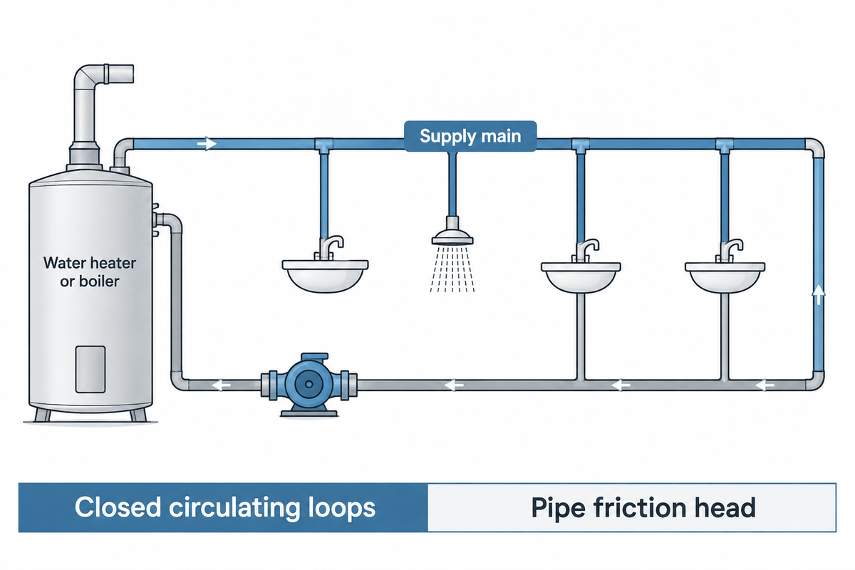
A recirculating pump moves water through the supply main and sends cooled water back to the water heater or boiler. In a conventional one-pipe plumbing system, turning a tap off leaves hot water in the branch. If that water loses Heat through the walls of the branch, it takes longer for the hot water to be delivered to the tap. The next time someone opens the tap, all that cooled water must drain to the sewer first. Fresh hot water is delivered only after the heater clears the dead leg. InterNACHI estimates that in the United States households waste 400 billion to 1.3 trillion gallons of water annually, while waiting for hot water to be delivered.
This problem is resolved by a hot water recirculation system which provides a hydraulic circuit from the farthest fixture. Routing water through a complete loop provides a return path to the water heater from which it was drawn. Thus, the gravity induced static lift in the return path balances the static lift in the supply path.
Why Do Closed Circulating Loops Only Pump Against Pipe Friction Head?
Closed circulating loops only pump against pipe friction head because downward return gravity cancels upward supply elevation lift. Process engineers on chemical engineering forums explain that a closed-loop circulator only needs to overcome friction head. It generates just enough pressure differential to push water past pipes, elbows, heat exchangers, and balancing valves.
Any dependable liquid recirculation circuit relies on four mechanical elements working together:
- Small domestic loops use glandless wet-rotor circulator pumps where the pumped water cools and lubricates the bearings. Higher-pressure commercial and industrial loops use dry-rotor inline or end-suction centrifugal pumps. According to Inspenet, API 610’s 12th edition was released in January 2021, approximately 11 years after the 11th edition. It updated service life, hydraulic selection, and pump data sheet criteria for heavy process centrifugal pumps.
- Installed on the return line, a spring-loaded Check valve allows water to flow in just one direction. If a Check valve is stuck open, then opening a hot tap allows water to flow backward through the return line and dilutes the hot water.
- According to InterNACHI, thermostatic loop temperature sensors and aquastats switch the pump on when line temperature drops below 85°F. They switch the pump off at 95°F, with adjustable setpoints from 77°F to 104°F.
- Pockets of trapped air rise to the highest points in the piping and don’t let low-head circulators exhaust their energy. An air vent releases the air pockets. Multi-branch commercial buildings use thermostatic balancing valves on each riser to prevent short-circuiting through the nearest branch.
Dedicated Return Line vs Thermal Bypass Crossover Valve Systems
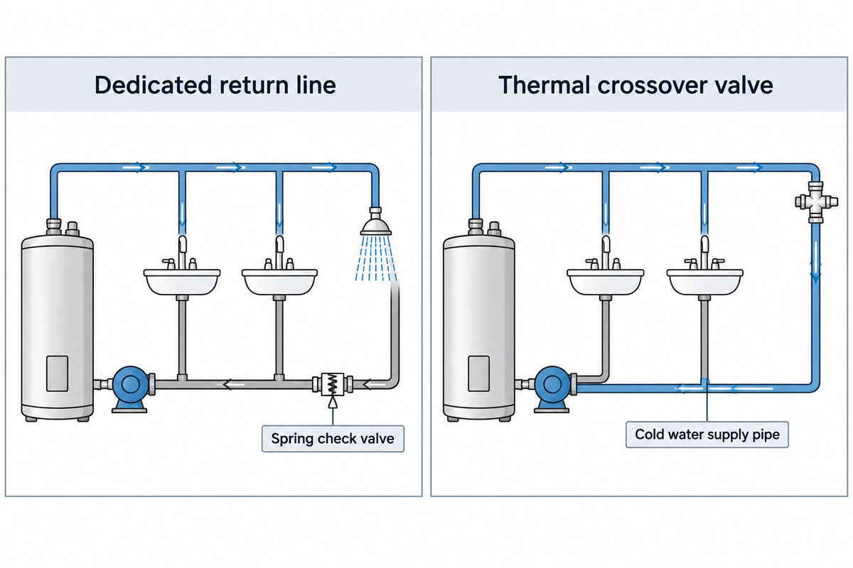
When designing or retrofitting domestic hot water recirculation, engineers select between two piping layouts. One option includes a dedicated return line, and the other option integrates a thermal crossover valve loop. Both approaches achieve reduced water waste at the tap, as documented by ENERGY STAR. The difference in the two piping layouts is that the return flow for a dedicated return line is routed through a separate pipe, whereas return flow for a thermal crossover valve is routed through the cold water supply pipe.
How Does a Dedicated Return Line Differ from a Thermal Crossover Valve?
A dedicated return line uses an additional third pipe to return water to the heater, and a thermal crossover valve uses the cold supply line to return water to the heater. The difference in piping structure impacts cost of installation, cold-tap water temperature, and commercial hygiene.
With a dedicated return line architecture, the plumber runs an insulated copper or PEX return pipe from the farthest branch. The circulator pump mounts on the return line pushing into the heater alongside isolation valves and a spring check valve. A dedicated return line carries return water back to the heater without using the cold-water distribution branches as the return path.
In a thermal crossover valve retrofit (comfort tee), plumbers don’t need to open drywall to run a third pipe. Instead, the pump is mounted on the water heater discharge or a more remote sink. A thermostatically actuated mixing valve (like the design in US Patent Application US20130340849A1) connects the hot and cold angle stops under the remote sink. As water in the hot line is cool, the crossover valve stays open. It mixes the cooled water in the cold line and directs it back to the water heater. The actuator closes the crossover port when hot water reaches the internal wax sensor (around 95°F).
Thermal crossover valves serve single-family residential retrofits and are avoided in healthcare and commercial ASHRAE 188 water management loops because they temporarily warm the cold-water return path. Warming cold supply piping into the 77°F-104°F range overlaps conditions for the growth of Legionella. The U.S. Centers for Disease Control and Prevention (CDC) note that keeping cold water below 77°F (25°C) helps limit the growth of Legionella in a building water system.
| Design Parameter | Dedicated Return Line (3-Pipe Loop) | Thermal Crossover Valve (2-Pipe Retrofit) |
|---|---|---|
| Piping Architecture | Cold supply + Hot supply + Dedicated insulated hot return line | Existing Cold supply + Hot supply bridged by under-sink thermostatic tee |
| Cold Tap Water Quality | Dedicated return piping avoids routing recirculated hot water through cold-water distribution branches | Cold tap briefly dispenses warm water (77°F–95°F) after a recirculation cycle |
| Commercial ASHRAE 188 Considerations | Allows hot-water return circulation and cold-water temperature control to be managed separately in ASHRAE 188 water management plans | Restricted to single-family residential retrofits; avoided in commercial and healthcare ASHRAE 188 water management plans |
| Primary Failure Mode | Unbalanced multi-branch flow or excessive velocity eroding copper elbows | Failed wax cartridge sticking open and causing continuous hot-to-cold crossover |
Circulating Loop Pumps vs Automatic Minimum-Flow Recirculation Valves (ARV)
In industrial plants, engineers must distinguish a circulating pump from a minimum-flow recirculation line. A circulating pump drives liquid around a distribution loop. A minimum flow recirculation line is needed to protect a high-energy centrifugal pump from low-flow conditions. Confusing these two systems causes inappropriate sizing of the valve, resulting in pump failure.
How Does a Circulating Loop Differ from a Minimum-Flow Protection Line?
A circulating loop uses a low-head pump to move conditioned liquid through a distribution system. A minimum-flow protection line, on the other hand, bleeds discharge fluid back to the suction vessel at a low load. In a boiler house or refinery, the main centrifugal pump is sized for peak process demand.
As WARE explains for industrial steam boilers, modulating feedwater pumps run continuously while the boiler feedwater valve modulates. When the boiler load drops, the main feedwater control valve throttles nearly shut. However, the centrifugal pump continues spinning at full speed. The absence of a recirculation line to return a minimum of feedwater to the deaerator causes the liquid in the pump case to overheat and flash to steam. The steam destroys the mechanical seals and impeller.
According to industrial centrifugal pump minimum-flow guidelines, Minimum Continuous Stable Flow (MCSF) is in the range of 10% to 60% of Best Efficiency Point (BEP). MCSF is influenced by factors like impeller energy density and suction specific speed. Our engineering guide on automatic recirculation valves, describes the minimum flow protection analysis by BBP Manufacturing, which identifies low-flow internal recirculation as the root cause of cavitation pitting below 25% of the BEP flow.
There are three methods used by plant engineers to maintain minimum flow in an industrial pump:
- A continuous fixed orifice recirculation line puts a restriction orifice plate in a permanent return line from the pump discharge to the feedwater tank. It’s mechanically simple, but continuously bleeds pressurized flow, and does so wastefully, even at full plant load. That continuous bleed wastes electrical horsepower and erodes the orifice plate, as boiler engineers note on Eng-Tips.
- A flow-sensing modulated control valve loop uses an electronic flow transmitter (Flow measurement loop) to read main discharge flow and signal a pneumatic return valve. The valve opens when flow approaches MCSF, saving energy at high load while requiring instrument air and control power.
- Installed directly on the pump discharge nozzle, a self-actuated automatic recirculation valve (ARV) combines a spring-loaded main check valve with a mechanically linked side return port. The return port automatically opens when process demand is less than MCSF.
Recirculation Loop Sizing Principles: Heat Loss, Flow Rate, and Copper Velocity Limits
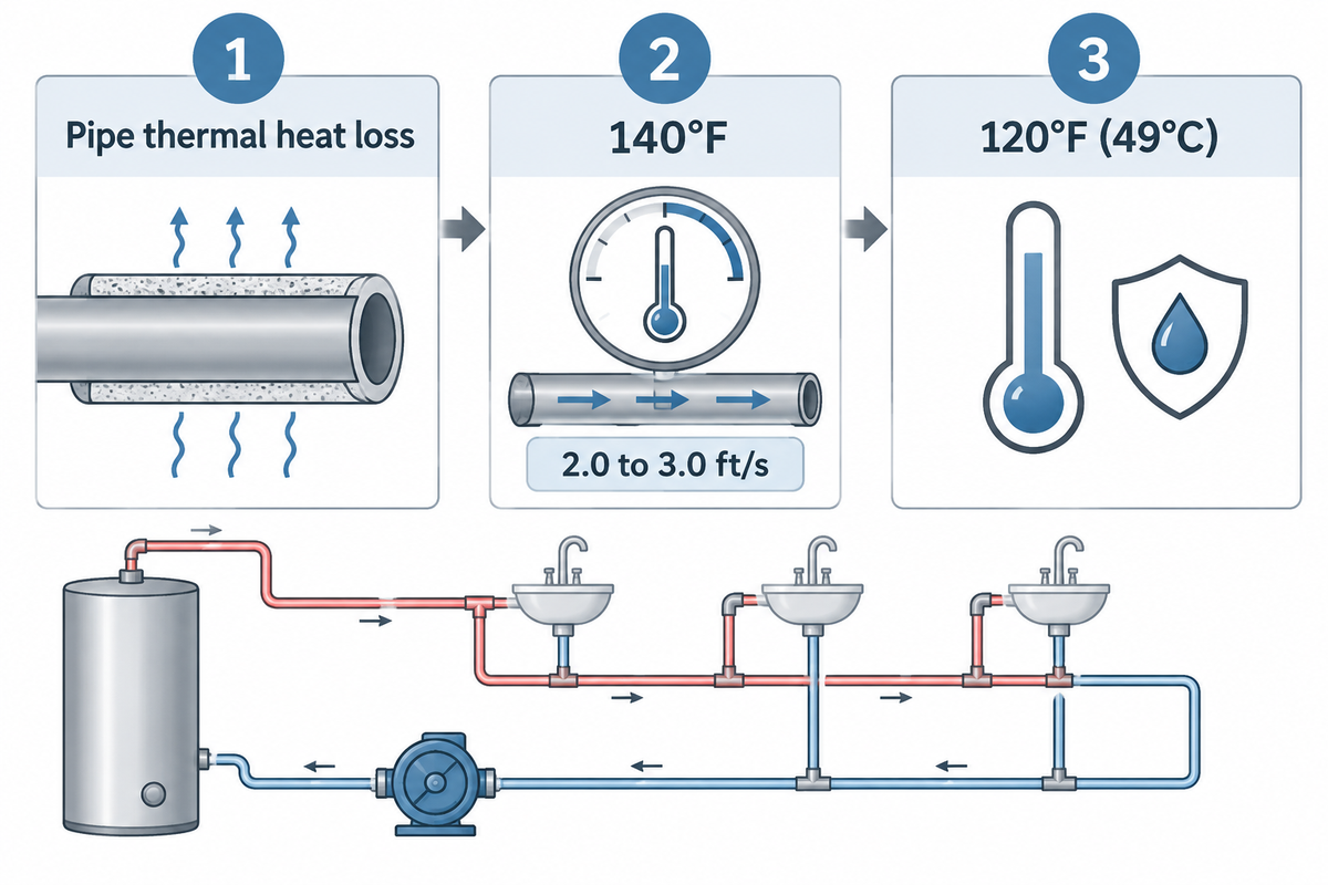
Main booster pumps are sized for peak fixture gallons per minute (GPM). By contrast, a domestic or commercial hot water recirculation pump is sized strictly to replace pipe thermal heat loss. Oversizing a circulator is one of the costliest errors in commercial Plumbing.
Why Does Oversizing a Hot Water Circulator Cause Copper Pipe Pinhole Leaks?
An oversized hot-water circulator can exceed the velocity limit appropriate to the water temperature and piping conditions, increasing the risk of erosion at elbows and tees.
To size a recirculation circuit properly, engineers first calculate the heat loss of the supply and return piping network. That calculation uses pipe diameter, length, water temperature, and fiberglass or foam insulation thickness. Next, engineers calculate the required circulating flow rate in GPM using the heat-loss flow relationship Q = q / (500 × ΔT). Here q represents the piping heat loss in BTU/hr and ΔT represents the design loop temperature drop in °F. The cited multifamily stakeholder proposals and next-generation smart ECM controllers use a target recirculation temperature drop of 5°F. Upward supply lift and downward return gravity cancel out in a closed loop. Required pump differential head is the total head loss through the highest-resistance supply-and-return circuit at its design flow, including piping, fittings, valves, and equipment, evaluated with the pipe friction loss formula. Motor electrical draw is verified with the pump power calculation formula. Pipe insulation affects heat loss and therefore sets the required circulation flow. Pump head then depends on design flow, pipe length, internal diameter, roughness, and losses through fittings, balancing valves, and equipment.
As reported in Consulting-Specifying Engineer and by Active Plumbing field personnel, excessive recirculation velocity results in severe erosion-corrosion of copper tubing. Cold-water copper piping typically uses design velocity limits in the range of 5 to 8 ft/s, with lower velocities reducing noise and erosion-corrosion risk. However, water heated above 140°F accelerates chemical oxidation and mechanical scouring, requiring designers to cap velocity at 2.0 to 3.0 ft/s. For this reason, the velocity in such applications should be restricted to 2.0 to 3.0 ft/s.
Commercial facility engineers must also satisfy strict Legionella hygiene rules. CRB Water reports that New Jersey’s Senate Bill S2188 was signed into law in September 2024. This legislation requires covered facilities to create a Legionella water management plan in accordance with ASHRAE 188 by September 12, 2026, and fully implement it by December 12, 2026. Covered facilities include hospitals, hotels and motels with 25 or more units sharing a centralized water heater, and residential high-rise buildings with six or more floors.
With water management programs, CDC operational guidance advises keeping circulating hot water at or above 120°F (49°C). Addendum bh to ASHRAE Standard 90.1-2025, according to HFM Magazine, mandates unoccupied setbacks in qualifying clinical spaces in health care facilities. Setbacks for those high air-change clinical spaces are already permitted under Standard 170-2025.
| Nominal Pipe Size (Type L Copper) | Max Recommended Velocity (≤140°F Water) | Max Recommended Velocity (>140°F Water) | Approximate Max Flow Cap at 2.5 ft/s | Commercial Water Management Note |
|---|---|---|---|---|
| 1/2-inch Type L Copper | 4.0 – 5.0 ft/s | 2.0 – 3.0 ft/s | ~1.8 GPM | Suitable for single-riser return branches; verify thermostatic balancing valve setting. |
| 3/4-inch Type L Copper | 4.0 – 5.0 ft/s | 2.0 – 3.0 ft/s | ~3.8 GPM | Standard main return header for light commercial loops where water management plans specify ≥120°F return water. |
| 1-inch Type L Copper | 4.0 – 5.0 ft/s | 2.0 – 3.0 ft/s | ~6.5 GPM | Used in multi-riser hotels and hospitals developing ASHRAE 188 plans under NJ S2188 (Sept/Dec 2026). |
Where Recirculation Systems Fit: Domestic Hot Water, Tankless, and Process Loops
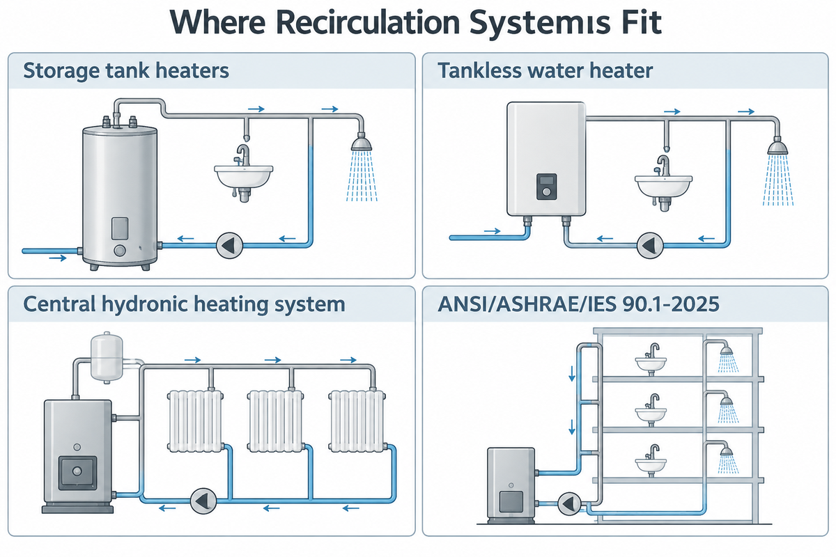
For residential, commercial, and industrial facilities, four primary duty profiles dominate.
1. Storage Tank vs Tankless Water Heater Recirculation
Continuous or timer-controlled return of water is easily managed by storage tank heaters. In the case of a loop, the storage tank acts as a thermal buffer for the returning amount of water. A tankless water heater may short-cycle when the recirculation heat load falls below its minimum firing output; compatible recirculation controls or a buffer tank can reduce repeated burner starts.
2. Commercial HVAC Hydronic Heating and Cooling Loops
Large commercial heating and cooling systems—including every central hydronic heating system—rely on closed loops. These systems circulate chilled or heated water between central plants and air handlers. According to ANSI, the new revision of ANSI/ASHRAE/IES 90.1-2025 incorporated over 100 addenda approved since the 2022 edition. These revisions address the energy efficiency and compliance requirements for buildings other than low-rise residential. The same is true with the 2025 edition of ANSI/ASHRAE 62.1. Federal motor and hydraulic regulations are also reshaping the circulator market. Other additions include emergency ventilation controls and a new demand control ventilation sequence. For high-flow commercial hydronic headers and district cooling plants, engineers often specify vertical split case pumps.
3. Industrial Evaporator, Slurry, and Chemical Process Loops
Continuous recirculation is commonly employed over long lengths of piping for chemical reactors, salt crystallizers and digesters. It provides for uniform heat transfer through shell and tube exchangers. For large flow rates at low total dynamic head, designers employ high-volume axial flow circulation pumps made of 316 stainless steel or duplex alloys. Closed-loop water recirculation provides major water savings in research laboratories. Georgia State University reported a 99.76% reduction in laboratory cooling water use, from single-pass tap water cooling, by implementing recirculating loops.
4. Cooling Towers and International Thermal Code Mandates
Open-loop cooling tower recirculation systems face tightening thermal efficiency and biological control standards worldwide. According to ICS Thailand, Thailand updated its 2026 Building Energy Code to enforce stricter thermal standards specifically for new or retrofitted facilities larger than 2,000 square meters. ICS Thailand states that these standards will likely have the biggest impact on the air conditioning and hot water systems used in large commercial and industrial spaces. Meanwhile, Envira points to Spain’s draft standard PNE 100030, which once published will be referred to as UNE 100030:2026. Until final publication, UNE 100030:2023 remains the reference technical standard complementing Royal Decree 487/2022 and Royal Decree 614/2024 for cooling towers.
Continuous, Timer, and On-Demand ECM Controls: Energy Cost and 2028 DOE Standards
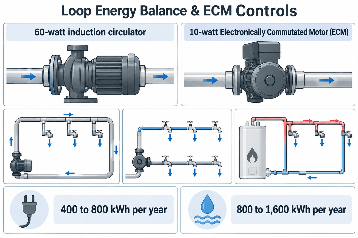
Many buyers assume that swapping a 60-watt induction circulator for a 10-watt Electronically Commutated Motor (ECM) pump makes 24/7 recirculation nearly free. While ECM wet-rotor motors significantly reduce pump electrical draw, the electricity consumed by the motor accounts for only a small fraction of total loop energy use.
Why Does Pipe Thermal Standby Loss Outweigh Pump Motor Wattage?
As reported by ENERGY STAR, and water heater efficiency studies, continuous operation of an uninsulated loop turns building piping into a heat radiator, increasing water heater standby energy use. To make up for the heat lost from the piping, the water heater is forced to cycle on and on. During summer cooling months, radiated pipe heat also adds parasitic load to the space cooling system.
Simultaneously, draining cooled water in a building without recirculation carries an upstream municipal energy penalty. The U.S. Department of Energy Building Science Education (BSESC) states that municipal treatment and pumping of wasted household hot-water standby volumes consumes 800 to 1,600 kWh per year. InterNACHI states a continuous residential recirculation pump consumes 400 to 800 kWh per year in pump electricity and piping heat loss. Timer-controlled and on-demand ECM systems cut daily runtimes significantly. Three-speed smart ECM controls with scheduled off-periods and a 5°F target temperature drop cut pump electrical draw by up to 94% over continuous AC induction units. In high-risk healthcare, hospitality and commercial buildings under ASHRAE 188 water management plans, where CDC guidance recommends keeping circulating hot water at or above 120°F (49°C) and recirculating continuously where possible, overnight timed shutoffs and on-demand standby modes aren’t permitted. Actual utility savings and payback periods are dependent upon local utility rates, fuel types, pipe insulation and installation costs. A recirculation system is cost effective when the value of water and energy saved is greater than the cost of the recirculation system and its operation:
- Continuous circulation with temperature control: CDC guidance recommends keeping circulating hot water at or above 120°F (49°C) and recirculating continuously where possible in high-risk commercial and healthcare buildings.
- Timer-controlled recirculation suits predictable residential or low-risk office schedules by shutting the pump off overnight, though residual hot water in the pipes still cools after shutdown.
- Smart 3-speed ECM and aquastat modulation with scheduled off-periods and a 5°F loop temperature drop target cut pump electrical draw by up to 94% as compared to continuous AC induction units, and ENERGY STAR endorsed demand controls further reduce overall heat loss in the loop.
- With occupancy sensor or push-button control, a homeowner activates a motion sensor to use the faucet. Demand control reduces piping heat loss by limiting circulation to brief heating cycles that end when the return pipe thermostat senses warm water, although the warmed pipes continue losing heat after shutdown.
Federal motor and hydraulic regulations are also reshaping the circulator market. According to DataIntelo, the global hot water recirculation pumps segment reached USD 1.42 billion in 2025 and is projected to reach USD 2.51 billion by 2034. Within the United States, according to Total Home Supply, the U.S. Department of Energy finalized new efficiency standards for circulator pumps under EPCA. The May 22, 2028 compliance date applies to circulator pumps within DOE’s regulated product definition, including covered models used in residential, commercial, and industrial applications. According to ECM PCB Stator, circulator pumps manufactured or imported from May 22, 2028 that fall within the rule’s power, fluid, and pump-type scope must meet a Circulator Energy Index (CEI) of 1.00 or better. Citing data submitted to DOE during rulemaking, only 33% of pump shipments were already compliant when the final rule was published. Manufacturers can redesign noncompliant models for continued production or discontinue them before the compliance date.
See the regulatory scope boundary under 10 CFR 431.465 (i) for the May 22, 2028 Circulator Energy Index (CEI ≤ 1.00) standard. The rule covers clean-water circulator pumps up to 5 HP (excluding submersible and header pumps) and excludes heavy industrial slurry or API 610 process pumps.
| Control Strategy | Daily Pump Runtime | Piping Thermal Standby Loss | 2028 DOE CEI ≤ 1.00 Alignment | Recommended Building Scope |
|---|---|---|---|---|
| Uncontrolled 24/7 Fixed-Speed AC Induction | 24 hours/day (8,760 hrs/yr) | Continuous piping heat loss | Covered models require CEI ≤ 1.00 | Legacy residential and commercial installations being upgraded to temperature or demand control |
| Continuous ECM + Aquastat / ΔT Modulation | Modulates speed to hold return ≥120°F where specified by the water management plan | Continuous piping heat loss; full pipe insulation reduces that loss | Covered models require CEI ≤ 1.00 | Hospitals, hotels, and high-rises using ASHRAE 188-aligned water management plans |
| Timer + Aquastat ECM Control | Scheduled occupied windows (shut off overnight) | Reduced; residual hot water still loses heat after shutdown | Verify model-specific CEI compliance where applicable | Single-family homes and low-risk commercial offices |
| On-Demand (Push Button / Occupancy Sensor + Thermostat) | Brief triggered cycles before fixture draw | Reduced; circulation is limited to brief cycles, though warmed pipes continue losing heat after shutdown | Covered models require CEI ≤ 1.00; recognized by ENERGY STAR | Residential storage and tankless water heater loops |
Troubleshooting Suction and Discharge Internal Recirculation Below BEP
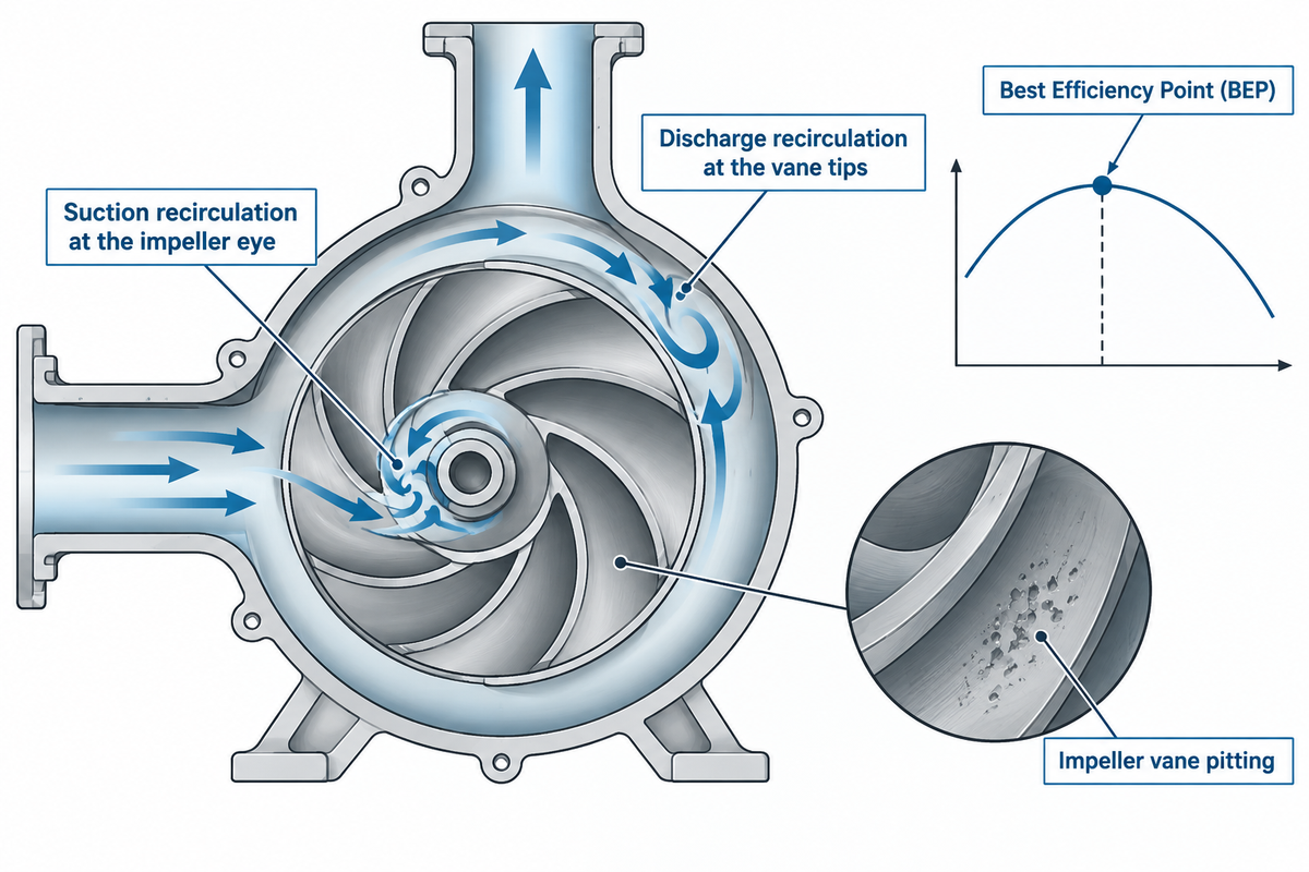
While external recirculation loops maintain normal circulation through building and plant piping, internal recirculation within a centrifugal pump is a destructive stall condition. If a downstream valve throttles a centrifugal pump to the left of its Best Efficiency Point (BEP), the through-flow velocity decreases sharply. However, impeller blades maintain their peripheral velocity.
What Causes Internal Recirculation Cavitation Inside a Centrifugal Impeller?
Internal recirculation cavitation happens when low flow causes the liquid to stall and flow in the reverse direction at the impeller eye or vanes. These reverse flow vortices create a region of low pressure that’s below the liquid’s vapor pressure. Vapor bubbles form and collapse violently against the metal vanes even when net positive suction head available (NPSHa) exceeds catalog limits.
As Pumps & Systems explains, internal recirculation divides into suction recirculation at the impeller eye and discharge recirculation at the vane tips. Internal recirculation can cause pressure pulsations and impeller vane pitting during low-flow operation. According to Pumps & Systems, high-energy impellers with large eye diameters and elevated Suction Specific Speed (Nss) experience suction recirculation closer to BEP. Intense vortex reversal also causes axial rotor shuttle and shaft deflection, which can increase wear on cartridge mechanical seals and close-clearance pump wear rings. To prevent or fix internal recirculation cavitation, plant engineers keep pump flow within the Allowable Operating Region (AOR) per ANSI/HI 9.6.3 and install a minimum-flow recirculation line or automatic recirculation valve (ARV) returning flow to the suction tank when process demand drops.
Rigorous factory testing catches these low-flow instabilities before field commissioning. According to Inspenet, API 610 (12th Ed.) requires that performance tests be performed in accordance with HI 14.6 or ISO 9906, expanding the test protocol from 6 to 9 mandatory points within the allowable operating region. It also specifies that NPSH testing must include determination of NPSH3 at points 2, 5, 6, 7 and 8, with H vs. NPSH(A) curves. As the Hydraulic Institute points out, NPSH3 test points indicate a 3% first-stage head drop from active cavitation. Safe Minimum Continuous Stable Flow (MCSF) must therefore be verified against the pump manufacturer’s certified curve rather than a single generic BEP percentage.
| Diagnostic Indicator | Suction Internal Recirculation | Discharge Internal Recirculation | Classic Vaporization Cavitation (Low NPSHa) |
|---|---|---|---|
| Operating Flow Region | Far left of BEP (below suction recirculation onset flow) | Far left of BEP (below discharge recirculation onset flow) | Frequently worsens right of BEP (high flow / runout) |
| Impeller Vane Pitting Pattern | Cavitation pitting in the impeller inlet eye zone during low-flow vortex reversal | Cavitation pitting near the outer discharge tips and shroud during low-flow stall | Cavitation pitting on the impeller vanes where local inlet pressure drops below vapor pressure due to insufficient NPSHa |
| Acoustic & Vibration Signature | Loud random crackling and popping from the suction nozzle; axial rotor shuttle | Metallic knocking at the volute cutwater; vane-pass pressure pulsations | Steady gravel-pumping roar; head and efficiency drop off sharply |
| Engineering Remedy | Open minimum-flow bypass/ARV, reduce impeller eye Nss, or add VFD speed control | Increase flow into POR, modify vane exit angle/volute gap, or install minimum-flow bypass | Increase suction vessel pressure, lower liquid temperature, or reduce suction line friction |
Engineering Specs, Certifications, and Piping Checklist for Selecting a Manufacturer
When acquiring circulating pumps for commercial HVAC plants, district energy loops, or industrial process lines, single-point catalog ratings aren’t sufficient. Purchasing personnel should evaluate pump manufacturers against current rotodynamic design and testing standards.
According to ANSI, ANSI/HI 14.3-2024 (Rotodynamic Pumps for Design and Application) provides guidance and recommendations for the general design and application of rotodynamic pumps. That scope covers centrifugal (radial), mixed, and axial flow types. It outlines accepted methods for evaluating hydraulic performance and designing supporting equipment while excluding detailed hydraulic design procedures. For petroleum and petrochemical loops, Inspenet notes that API 610 12th Edition expands performance testing under HI 14.6 or ISO 9906 from 6 to 9 mandatory points in the allowable operating region and requires NPSH3 determination at points 2, 5, 6, 7, and 8. In addition, Teflow Pumps notes that API 610 12th Edition mechanical seal chambers are harmonized with API 682 4th Edition. API 610 and API 682 coordinate seal interfaces; cartridge seals fit when their configuration and dimensions match the pump shaft and seal chamber. For U.S. clean-water circulators up to 5 HP manufactured or imported from May 22, 2028, buyers should also verify 10 CFR 431.465(i) CEI ≤ 1.00 compliance (which excludes submersible pumps, header pumps, and heavy industrial slurry or API 610 process pumps).
| Verification Item | Applicable Standard / Benchmark | What to Request in the RFQ Package |
|---|---|---|
| 1. Operating Window & Minimum Flow Limits | ANSI/HI 9.6.3 & ANSI/HI 14.3-2024 | Full Q–H curve marking BEP, Preferred Operating Region (POR), Allowable Operating Region (AOR), minimum continuous stable flow (MCSF), and minimum continuous thermal flow as separate limits. |
| 2. Performance & NPSH3 Witness Testing | HI 14.6 / ISO 9906 & API 610 12th Ed. | For petroleum/petrochemical duties, 9-point performance curve within the allowable operating region and NPSH3 test verification at points 2, 5, 6, 7, and 8 with H vs. NPSH(A) curves. |
| 3. Wetted Metallurgy & Fluid Compatibility | ANSI/HI 14.3-2024 & Process Duty Specs | Verify wetted alloy selection (such as 316 stainless steel or duplex alloys used in axial-flow and split-case circulation loops) against fluid temperature, velocity, and corrosion risks. |
| 4. Seal Chamber & Bearing Isolation | API 682 4th Edition (Harmonized with API 610 12th Ed.) | Verify that cartridge mechanical seal configuration and dimensions match the pump shaft and API 682 seal chamber interface. |
| 5. Clean-Water Circulator Efficiency | U.S. DOE 10 CFR 431.465(i) (May 22, 2028) | For covered clean-water circulators up to 5 HP manufactured or imported into the U.S. from May 22, 2028 (excluding submersible pumps, header pumps, and heavy industrial slurry or API 610 process pumps), verify CEI ≤ 1.00 compliance. |
| 6. Minimum-Flow Bypass & Valve Integration | Plant P&ID & Deaerator Backpressure Specs | Confirm whether the pump requires an external automatic recirculation valve (ARV) or modulating minimum-flow line. |
| 7. Copper Loop Velocity & Balancing Valves | Copper Erosion Limits (≤2.0–3.0 ft/s above 140°F) | Confirm branch flow rates stay within recommended velocity limits and specify thermostatic balancing valves and spring check valves on multi-riser returns. |
| 8. Commercial Hygiene & Return Temperature Control | ASHRAE 188 / NJ S2188 & CDC Guidance | Verify that aquastat sensors and pump controls maintain circulating hot water at or above 120°F (49°C) where specified by the building water management plan. |
| 9. HVAC Hydronic & Cooling Tower Energy Compliance | ANSI/ASHRAE/IES 90.1-2025 & UNE 100030:2023 | Align commercial hydronic and cooling-water pump selections with applicable building energy codes and cooling tower technical standards. |
If your engineering team is designing an industrial cooling loop, evaporator circulation stage, or boiler feedwater system, contact BBP Manufacturing’s pump engineering team and provide your flow rate, differential head, fluid temperature and suction pressure conditions for a curve-verified selection.
Frequently Asked Questions
1. What does recirculation mean in a plumbing or industrial pumping system?
Within plumbing and the discipline of industrial fluid engineering, recirculation is the continuous or on-demand movement of liquid through a closed piping loop back to its heating or supply source. Domestic hot water systems use a recirculation pump to pull cooled water from the supply main and return it to the water heater. Hot water is available at the fixtures and isn’t lost running down the drain. Industrial plants use recirculation loops to keep process fluids at a uniform temperature, keep a slurry in suspension, and to circulate minimum flow back to the suction side of the system.
2. Is a hot water recirculation pump worth it, and does it increase energy bills?
Compared to a system with continuous circulation, an on-demand recirculation system reduces water waste and distribution heat loss. It provides a financial return when the value of water and energy savings exceeds installation and operating costs. While a modern Electronically Commutated Motor (ECM) circulator draws only 5 to 25 watts, running an uninsulated loop 24/7 increases water-heater standby heat loss. An insulated loop paired with smart or occupancy sensor controlled aquastats provides rapid hot water and reduces annual energy use.
3. Can you install a hot water recirculation system without a dedicated return line?
Yes, existing homes without a dedicated return pipe can use a thermal crossover valve (often called a comfort tee) installed under the farthest sink. The circulator pump pushes water down the hot supply line. The thermostatic crossover valve temporarily routes cooled water into the cold-water supply pipe to return to the heater. Once hot water reaches the valve (around 95°F, adjustable from 77°F to 104°F), the internal thermal actuator closes the return port. The main trade-off is that the cold tap briefly dispenses warm water right after a cycle.
4. What is the difference between a recirculation pump and an automatic recirculation valve (ARV)?
A recirculation pump is an active motor-driven machine that moves liquid around a loop, whereas an automatic recirculation valve (ARV) is a self-actuated protection valve on a centrifugal pump discharge. When the flow through a centrifugal pump drops below the pump’s Minimum Continuous Stable Flow (MCSF), the ARV opens a bypass and returns liquid to the storage tank to prevent recirculation inside the pump.
5. Why does internal recirculation happen inside a centrifugal pump at low flow?
Internal recirculation occurs inside a centrifugal pump when downstream throttling forces the pump to operate far left of its Best Efficiency Point (BEP). This is also known as Centrifugal pump Stall. Although the impeller of a pump continues to spin at design speed, the flow of liquid through the pump drops drastically. As a result, the liquid strikes the impeller at a high stall angle. Flow separates and reverses into high-speed vortices at the impeller eye (suction recirculation) or vane exit tips (discharge recirculation). Cavitation occurs if local pressure in these vortices drops below the liquid’s vapor pressure. This causes loud crackling sounds and vane pitting.
References & Sources
- U.S. EPA / DOE ENERGY STAR, Demand Hot Water Recirculating System Technical Overview
- U.S. Department of Energy BSESC, Hot Water Recirculation and Demand Control Energy Basics
- U.S. Code of Federal Regulations, 10 CFR 431.465 Circulator Pumps Energy Conservation Standards
- Total Home Supply, U.S. DOE May 22, 2028 Circulator Pump Efficiency Standards
- ECM PCB Stator, DOE Circulator Energy Index (CEI ≤ 1.00) and Compliance Analysis
- Inspenet, API 610 12th Edition Standardization, Performance Testing, and NPSH3 Verification
- ANSI / Hydraulic Institute, ANSI/HI 14.3-2024 Rotodynamic Pumps for Design and Application
- Hydraulic Institute, The Basics of NPSH and Pump Operating Regions
- Pumps & Systems, Why Suction and Discharge Recirculation Cavitation Occurs and Ways to Treat It
- CRB Water, New Jersey Senate Bill S2188 and ASHRAE 188 Legionella Water Management Deadlines
- U.S. CDC, Routine Monitoring Guidance for Control of Legionella in Hot and Cold Water Distribution
- Consulting-Specifying Engineer, Recirculating Hot Water Velocity and Copper Pipe Erosion-Corrosion
- InterNACHI, Hot Water Recirculation Systems Inspection and Thermostatic Setpoints
- WARE, What Are Boiler Feed Pump Recirculation Lines?
- ANSI, ANSI/ASHRAE/IES Standard 90.1-2025 Energy Standard Overview