Get in Touch with BBP

Updated November 2026
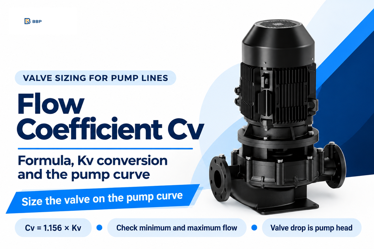
The flow coefficient (Cv) of a valve represents the number of US gallons per minute of 60 °F water that passes through it with a pressure drop of 1 psi across the valve. On a pumped line, that one number determines how many psi the valve takes from the pump at the duty flow, and therefore where the pump runs on its curve. The definition uses a flow rate of water because water is the reference fluid; any other liquid flow is scaled with its specific gravity.
Short answer: Flow coefficient Cv = Q × √(SG ÷ ΔP), where Q is in US gpm and ΔP is in psi. A valve taking 200 gpm of water at a 10 psi drop needs an operating Cv of 63.2. Size the valve so that the required Cv at minimum and maximum pump flow remains in its working travel, about 10% to 90% for a globe valve.
Quick Specs
| Cv test basis | US gpm of 60 °F water at a 1 psi drop |
| Kv test basis | m³/h of water at a 1 bar drop |
| Conversion | Cv = 1.156 × Kv; Kv = 0.865 × Cv |
| Liquid formula | Q = Cv × √(ΔP ÷ SG) |
| Head per psi (water) | 1 psi = 2.308 ft |
| Sizing standard | ANSI/ISA-75.01.01-2012 (IEC 60534-2-1 MOD) |
Key points
- A larger Cv isn’t a safer buy on a pump line: an over-sized valve can run close to its seat, where a small stem move can give a large flow change.
- Flow increases with the square root of the pressure drop, so doubling the drop results in approximately 41% more flow, not double.
- Every psi the valve takes is pump head you paid for: 400 gpm through a 25 psi drop burns about 4.35 kW of hydraulic power.
- Because the valve drop changes with flow, the Cv you need at minimum and maximum flow can differ by more than four to one.
Flow Coefficient Cv: Definition, Units and the Kv Equivalent
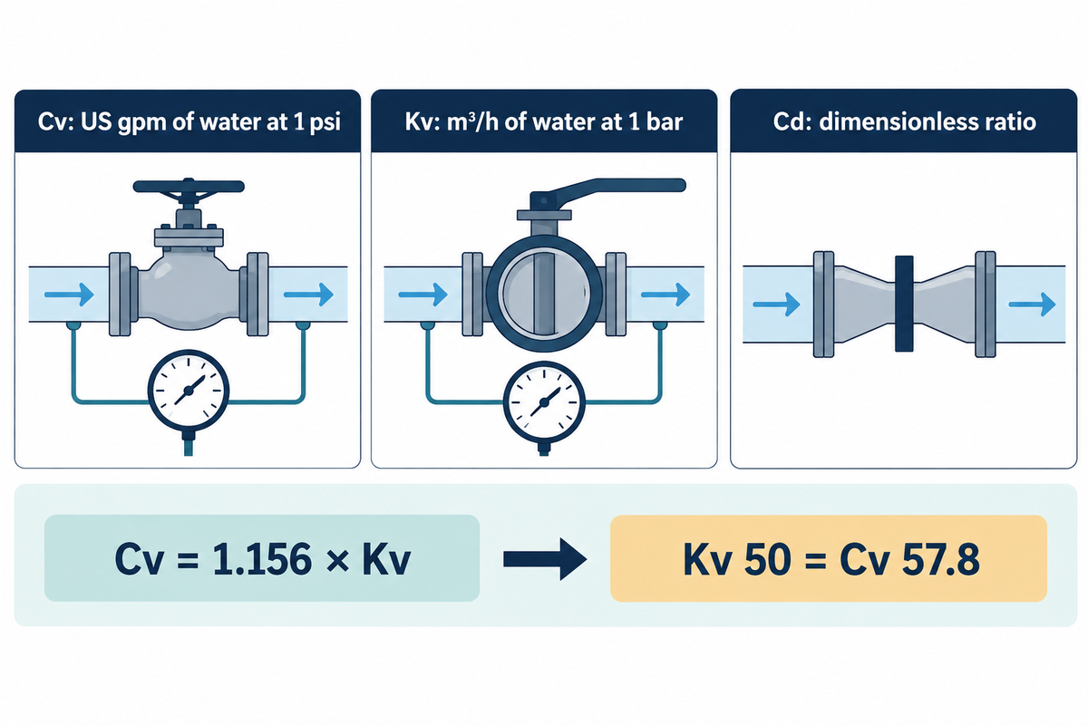
A valve flow coefficient is a capacity rating: the gallons of water per minute that flow through the valve when the pressure drop across it is exactly 1 psi. A Cv of 10 therefore means 10 US gpm of water at a 1 psi pressure drop, and a higher Cv means more flow capacity at the same drop.
The test basis is fixed so that two valves can be compared on the same sheet. Kimray, a control-valve maker, defines it as the volume of water at 60 °F in US gallons that will flow through a valve per minute with a pressure drop of 1 psi across the valve. One pound per square inch is the reference drop, and the water flow at that drop is what the Cv number counts. The rated Cv on a datasheet is the fully open value. As the stem opens, the valve’s flow coefficient climbs from near zero to that maximum, so the valve’s flow coefficient at any opening is a fraction of the rated number.
The metric twin is Kv: the flow of water in m³/h at a 1 bar pressure drop. A valve with Kv 10 passes 10 m³/h at 1 bar. Cv and Kv describe the same flow capacity in two unit systems, which is why European and US offers for the same valve can show numbers that look 16% apart.
| Coefficient | Flow unit | Reference drop | Has units? |
|---|---|---|---|
| Cv | US gpm of 60 °F water | 1 psi | Yes (gpm/√psi) |
| Kv | m³/h of water | 1 bar | Yes (m³/h/√bar) |
| Cd | ratio of actual to ideal discharge | Not applicable | No (dimensionless) |
What are the units for Cv?
Cv is measured in US gallons per minute per square root of psi, because the defining equation is written in terms of flow divided by the square root of the pressure drop. In practice the unit is left off and Cv is quoted as a bare number, such as 47 or 117, always meaning gpm of water at 1 psi across the valve.
Because it’s a bare number, it can cause confusion when different systems are mixed. A metric datasheet quoting Kv 50 and a US spec asking for Cv 50 describe different valves: Kv 50 equals Cv 57.8. Write the coefficient name, not only the number, on every RFQ line.
The Cv Formula for Liquids, Worked Through for a Pump Discharge
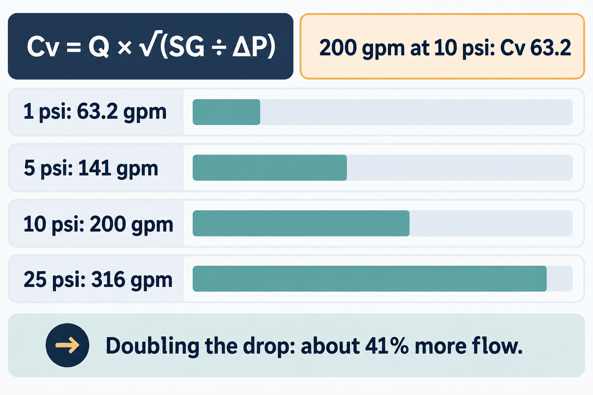
For a non-choked liquid, the required Cv equals the flow rate Q in US gpm, multiplied by the square root of the specific gravity divided by the pressure drop in psi: Cv = Q × √(SG ÷ ΔP). Water at 200 gpm with 10 psi across the valve would need an operating Cv of 63.2.
The working is short enough to check by hand. SG ÷ ΔP = 1 ÷ 10 = 0.1; the square root of 0.1 is 0.316; 200 × 0.316 = 63.2. Published Cv data use the pressure drop across the valve between set pressure taps upstream and downstream. A valve with a pressure drop of 10 psi at 200 gpm therefore has a Cv flow rating of 63.2 at that opening. The same relationship between flow and pressure drop turns around two ways. To calculate the flow rate through a valve whose Cv you know, use Q = Cv × √(ΔP ÷ SG). To find the pressure drop at a given flow, use ΔP = SG × (Q ÷ Cv)². Pressure drop and flow are tied by a square law, but flow is directly proportional to Cv, so at a given pressure drop a valve with twice the Cv passes twice the water through the valve.
Specific gravity matters more than it looks. A brine at SG 1.2 flowing at 200 gpm and 10 psi needs a Cv of 69.3, about 10% more than water, since the heavier liquid needs more flow path for the same psi pressure drop.
On a centrifugal pump discharge, ΔP is not the pump’s discharge pressure. It is the pressure left for the valve after pipe friction, fittings, elevation and the downstream pressure have taken their share at that flow. Satish Mathur of Bechtel, writing in Pumps & Systems, calls it common practice in pump systems to allow a minimum of 10 to 15 psi for the control valve, and checks that the pump still provides it at maximum flow. Where it stops: the formula assumes turbulent, non-flashing Newtonian liquid in a valve the same size as the pipe. The type of flow matters. Viscous liquids and very low flow rates need the non-turbulent correction. Reducers on either side of a smaller valve need the piping geometry factor. The IEC 60534-2-1 liquid equations do not cover slurries or liquid-solid mixtures. For gas, steam or a drop near the choked limit, use the full ISA-75.01 equations.
How do I convert a Cv value to GPM?
A Cv value converts to gallons per minute with Q = Cv × √(ΔP ÷ SG), with ΔP in psi and SG relative to water, for turbulent, non-choked liquid. A Cv 63.2 valve passes 63.2 gpm of water at 1 psi, 141 gpm at 5 psi, 200 gpm at 10 psi and 316 gpm at 25 psi.
The part most buyers miss is the square root. Going from 10 to 25 psi multiplies the drop by 2.5, but flow only by 1.58, and doubling the drop approximately increases flow by 41%. That’s why a valve that falls short of the desired flow is rarely fixed by adding pump pressure. Each extra psi across the valve adds cost, and only a fraction of it is returned as flow.
| Pressure drop | √ΔP | Flow |
|---|---|---|
| 1 psi | 1.00 | 63.2 gpm |
| 5 psi | 2.24 | 141 gpm |
| 10 psi | 3.16 | 200 gpm |
| 25 psi | 5.00 | 316 gpm |
Cv vs Kv vs Cd: Converting Between Datasheets
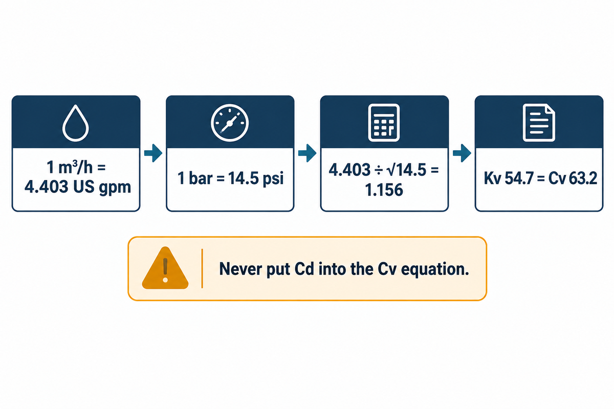
Kv converts to Cv by a factor of 1.156, and Cv converts to Kv by multiplying by 0.865. The same 200 gpm, 10 psi duty point works out to Kv 54.7 in metric units, and 54.7 × 1.156 returns the Cv value of 63.2, so either kv flow coefficients sheet sizes the same valve.
The factor comes straight from the unit change: 1 m³/h is 4.403 US gpm and 1 bar is 14.5 psi, and 4.403 ÷ √14.5 = 1.156. Cv and Kv use different reference water temperatures, and 1.156 is the unit conversion between them.
To compare a metric datasheet to a US spec sheet, either compute Kv from the flow in m³/h and the bar pressure drop, or convert the Cv by dividing it by 1.156. Both methods give the same final result. Keep three significant figures until the final step. Small mismatches creep in from early rounding.
What is the difference between Cv and Cd?
Cv is a dimensional capacity number for a whole valve, while the discharge coefficient Cd is a dimensionless ratio of the actual discharge to the ideal discharge through a nozzle or other constriction. Cv grows with valve size; Cd describes how efficiently a given opening passes flow.
Orifice plates and flow meters are rated with Cd, since the area of the orifice is known; valves are rated with Cv, as their internal flow path is too complex to be defined with one area. Never use a Cd value in the Cv equation; a Cd value less than 1 is an efficiency ratio, not a small valve.
Where a Control Valve Sits on the Pump and System Curves
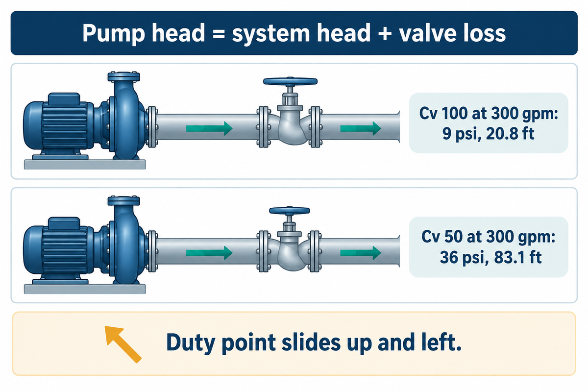
Throttling a control valve increases its contribution to the system head loss, and the pump then settles where its head curve meets the steeper system curve. At 300 gpm, a valve running at an operating Cv of 100 takes 9 psi, which the U.S. Department of Energy conversion turns into 20.8 ft of head.
The conversion is the DOE figure for water: a pressure drop of 1 psi equals a head loss of 2.308 ft. Close the same valve to an operating Cv of 50 and the drop at 300 gpm becomes (300 ÷ 50)² = 36 psi, or 83.1 ft. The pump can’t add 62 ft on demand, so the duty point slides up and left along its curve until the pump head equals system head plus valve loss at a lower flow. Mathur states the rule directly: in a pump and control valve system, system head plus control valve loss has to equal pump head.
In an unbranched line, fluid flow through the pump and the valve is the same flow, and throttling changes both flow and head as the operating point moves. That’s also why buyers misread throttling. Engineers on Eng-Tips describe it as the duty point moving up the curve to the left: flow falls and pressure at the discharge rises. The valve doesn’t “remove” flow; it raises the resistance the pump has to work against. The Hydraulic Institute’s system-curve guide lists control losses alongside static head, pressure head and pipe friction for the same reason.
Two practical steps follow. First, include the valve drop at maximum flow when you size the pump, or the commissioned flow comes in short; the pump sizing calculation worksheet adds it as a separate line. Second, check the curve at minimum flow, where a centrifugal pump’s head is highest and the valve has to absorb the difference. For pressure-boosting duties, BBP’s booster and pipeline line, which includes its vertical inline pump range, is listed for flows up to 2,500 m³/h and heads up to 200 m, VFD compatible, with ISO 5199 and API 610 OH3 options, so the valve drop can be checked against a real curve before ordering. High-head lines such as boiler feed use multistage pumps, which BBP also builds; there a 15 psi valve drop is a small share of the total. Loops that send part of the flow back to suction, such as recirculation loops, add one more branch to the same calculation.
Valve Sizing by Cv: Opening Range, Authority and Margin
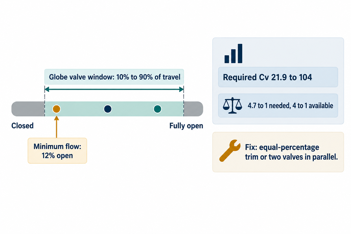
Valve sizing starts from the required Cv at minimum, normal and maximum flow, then picks the valve whose Cv curve keeps all three inside a working window. For sliding-stem globe valves that window is 10% to 90% of travel in Gregory McMillan’s ISA guidance and 20% to 80% in Kimray’s; for rotary valves it’s about 20° to 50° of rotation.
The ISA figures come from Gregory McMillan’s control-valve guidelines: “For sliding stem valves, the minimum and maximum valve positions are typically 10% and 90%, respectively.” Many rotary valves work between 20 and 50 degrees of disk or ball rotation. Kimray, a valve maker, recommends the tighter 20% to 80% for its regulators. Treat the window as a first screen: a valve inside it can still control poorly if its flow characteristic doesn’t suit the installed system.
Applying Cv to a pump line means checking a band, not one number. The proper Cv is the rated Cv value of a valve whose curve covers the low and high flow within the control range. Choosing a valve on the design point alone is how most control problems start, and Cv selection by catalog size (valves with Cv above the duty, rounded up) is how they get worse. The correct Cv value at maximum flow should still leave some travel in reserve, so the correct valve can be smaller than the pipe it resides in.
Kimray’s own example shows the process. Their 2-inch regulator has a maximum Cv of 47 and their 3-inch unit 117. A required Cv of 14 fits the 2-inch valve but sits at 12% of the 3-inch valve’s capacity (14 ÷ 117); a required Cv of 47 is the 2-inch valve fully open, so it needs the 3-inch. A Cv of 35 fits both, and Kimray chose the 3” because 35 is closer to the middle of the curve.
The pressure share given to the valve is the second number, and published rules disagree. In a Control Global Q&A, Béla Lipták sizes a valve by giving it 25–30% of the friction drop at 75% of its Cv. In the same column, R. Russell Rhinehart sets the Cv so that an equal-percentage valve 70% open passes nominal flow with a drop equal to 30% of the piping friction losses, excluding elevation and terminal pressures. The reader’s question that opens the column quotes a handbook rule of 50% of the friction loss. The 50% allowance is twice the 25% one on the same friction basis, while the 10 to 15 psi figure is a common practice, not a requirement. Whatever rule you start from, the drop you can actually give the valve is the pump head minus the static and friction head at each sizing flow; work it out at those flows and put the same numbers in every offer.
Min-to-Max Cv Travel Test
The Min-to-Max Cv Travel Test evaluates one valve against all three flows instead of just the design flow. In the example below, a pump line flows from 120 to 345 gpm and the valve drop falls from 30 psi at the minimum flow to 11 psi at the maximum since the head of the pump drops as the flow increases.
| Flow point | Flow | Valve drop | Required Cv | % of rated Cv | Verdict |
|---|---|---|---|---|---|
| Minimum | 120 gpm | 30 psi | 21.9 | 12% | Fails 20–80%; at edge of 10–90% |
| Normal | 300 gpm | 15 psi | 77.5 | 43% | Inside window |
| Maximum | 345 gpm | 11 psi | 104.0 | 58% | Inside window |
Assumed inputs: water, SG 1.0, linear trim, so % of rated Cv stands in for % of travel. The required Cv spans 21.9 to 104, a 4.7 to 1 range, while a 20–80% window covers only 4 to 1. Under Kimray’s 20%–80% window no single linear valve fits all three points. Under McMillan’s 10%–90% window it fits only if the valve still controls well at 12% open. Two fixes widen the range: an equal-percentage trim, which gives finer resolution at low flow, or a small and a large control valve in parallel. If the low point exists only to protect the pump, an automatic recirculation valve handles minimum flow separately. A higher Cv valve “for margin” makes the low-end row worse. That’s the common oversizing mistake: the valve runs near its seat, where a small stem move gives a large flow change and control accuracy suffers.
Cv by Valve Type: Ball, Butterfly, Globe and Gate Compared
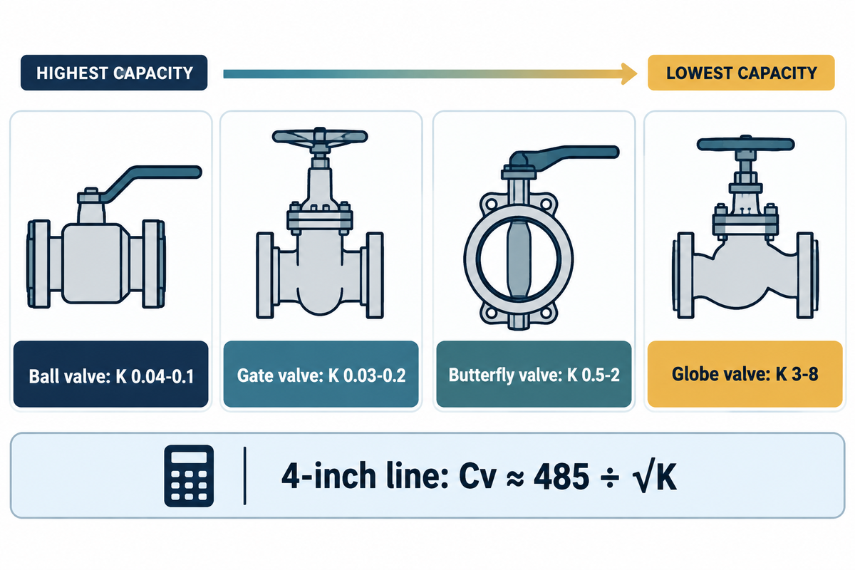
Overall Cv for a given valve size decreases in the order: ball and gate > butterfly > globe. For a 4-inch line, the DOE’s head-loss coefficients translate to about 1,500–2,400 Cv for a fully open ball valve and 170–280 for a globe valve.
The DOE pumping tip sheet lists fully open head-loss coefficients K for water: globe 3–8, ball 0.04–0.1, gate 0.03–0.2, butterfly 0.5–2 and check 2, and warns that values can vary by 30% to 50%. K converts to Cv with Cv = 29.9 × d² ÷ √K, where d is the bore in inches. That constant can be checked from the DOE’s own figure: at 1 psi the head is 2.308 ft, velocity becomes √(2 × 32.174 × 2.308 ÷ K) = 12.19 ÷ √K ft/s, and flow in gpm is velocity × d² ÷ 0.4085, which gives 29.8 d² ÷ √K. For a 4-inch Schedule 40 bore of 4.026 in, 29.9 × 4.026² ≈ 485, so Cv ≈ 485 ÷ √K.
| Valve or fitting type | K (fully open) | Equivalent Cv, 4-in | Typical role |
|---|---|---|---|
| Gate valve | 0.03–0.2 | 1,084–2,798 | Isolation |
| Ball valve | 0.04–0.1 | 1,533–2,423 | Isolation, V-port control |
| Bell-mouth inlet | 0.05 | 2,167 | Tank outlet |
| Long radius elbow | 0.1–0.3 | 885–1,533 | Routing |
| Standard elbow | 0.2–0.3 | 885–1,084 | Routing |
| Butterfly valve | 0.5–2 | 343–685 | Large-line control |
| Square-edged inlet | 0.5 | 685 | Tank outlet |
| Discharge into tank | 1 | 485 | Line end |
| Check valve | 2 | 343 | Backflow stop |
| Globe valve | 3–8 | 171–280 | Fine throttling |
The globe valve has the lowest Cv because its flow path turns twice; its trim characteristic and actuator, not the turns themselves, are what make it a good throttling valve. A full-port ball valve passes ten times more water when open but gives coarse control in its first few degrees of rotation, so a V-port ball is the usual compromise for control duty. The DOE adds the energy side: significant losses occur with globe valves even when they’re fully open, so a valve kept only for isolation should be a low-loss type. Some pressure reducing valves and regulators use globe-style bodies; regulator maker Cashco quotes typical regulator Cv of 0.05–0.5 for small ports and 5–10 for large ports. For any of these, the flow performance you get depends on where the control valve’s flow curve sits at your duty, not on the fully open number alone.
Throttling Valve vs Variable Speed Drive: What the Valve Drop Costs
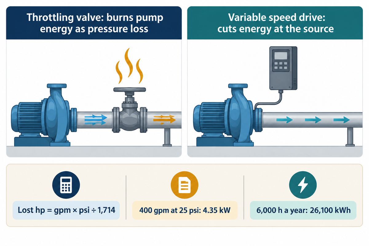
A throttling valve controls flow by burning pump energy as pressure loss, while a variable speed drive cuts the energy at the source by slowing the pump. The cost of the valve is easy to price: hydraulic horsepower lost equals gpm × psi ÷ 1,714, so 400 gpm through a 25 psi drop wastes 5.83 hp, or 4.35 kW.
The constant comes from the DOE formula, fluid horsepower = gpm × head in ft × SG ÷ 3,960, with head in psi multiplied by 2.308; 3,960 ÷ 2.31 = 1,714. Over 6,000 running hours, that 4.35 kW of hydraulic loss is 4.35 × 6,000 = 26,100 kWh a year, before pump, motor and drive losses are added on top. The same arithmetic, filled in for nine common duties, gives the Valve Drop Energy Bill below; the pump power formula article covers the motor side of the conversion.
| Flow | Valve drop | Hydraulic loss | Hydraulic loss | Energy per year |
|---|---|---|---|---|
| 100 gpm | 10 psi | 0.58 hp | 0.44 kW | 2,610 kWh |
| 100 gpm | 25 psi | 1.46 hp | 1.09 kW | 6,530 kWh |
| 100 gpm | 50 psi | 2.92 hp | 2.18 kW | 13,050 kWh |
| 200 gpm | 10 psi | 1.17 hp | 0.87 kW | 5,220 kWh |
| 200 gpm | 25 psi | 2.92 hp | 2.18 kW | 13,050 kWh |
| 200 gpm | 50 psi | 5.83 hp | 4.35 kW | 26,100 kWh |
| 400 gpm | 10 psi | 2.33 hp | 1.74 kW | 10,440 kWh |
| 400 gpm | 25 psi | 5.83 hp | 4.35 kW | 26,100 kWh |
| 400 gpm | 50 psi | 11.67 hp | 8.70 kW | 52,210 kWh |
Assumed inputs: water at SG 1.0, constant flow and 6,000 h a year; the energy is hydraulic power only, so the motor input is higher by the pump, motor and drive losses. For variable duty, find the energy by multiplying the flow × drop for each operating band, multiplying that product by the hours in that band, and adding the bands; averaging flow and drop first gives the wrong total. The table counts the hydraulic energy dissipated in the valve drop. It isn’t a bill saving: after a speed retrofit, the saving is the difference in metered power before and after, which also moves with pump, motor and drive efficiency.
“When systems are being retrofitted with ASDs, the control valve can be removed from the system to eliminate unnecessary pressure drops.”
U.S. Department of Energy, Pumping Systems Tip Sheet #10, March 2007
Throttling control valve
- Fast, local flow and pressure control
- Wastes gpm × psi ÷ 1,714 hp across the valve
- Still needed for isolation and minimum-flow duty
Variable speed drive
- Cuts power roughly with speed cubed on friction-dominated lines
- Higher first cost per kW of motor
- Savings shrink where static head dominates
The Hydraulic Institute publishes one case study. A water system with two 15 kW (20 hp) pumps held pressure with a relief valve that sent surplus water back to the tank. A VFD with a pressure transducer replaced that control. Energy fell from 134 to 16 MWh a year, and the installation paid back in 6 months. That’s one reported system, not a general saving rate. Still, it shows why a large, steady valve drop is worth a speed-control study. The Hydraulic Institute case study also sets the limit: VFD control suits systems with variable flow demand where pressure losses come mainly from pipe friction. On a line where most of the head is lift, slowing the pump soon reaches the static head and the saving stops. The choice follows from that: if flow varies and friction makes up most of the head, study a VFD and keep a valve only for isolation; if flow is steady or lift dominates, keep the control valve and size it with the travel test above. The VFD pump control guide covers where speed control fits, and the pump affinity laws show how head and power fall with speed.
Cavitation and Choked Flow: Where the Cv Formula Stops
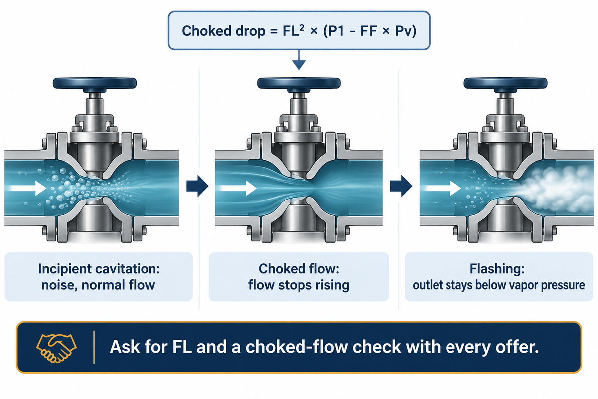
For a liquid flowing through a valve without attached reducers, flow reaches its limit at a pressure drop of FL² × (P1 − FF × Pv) when inlet pressure, valve opening and liquid properties are held fixed. Further lowering the outlet pressure adds no flow. FL is the dimensionless pressure recovery factor and FF the liquid critical pressure ratio factor; P1 and Pv are inlet and vapor pressure in absolute terms. Cavitation may occur before the flow is limited.
The choked-flow equation is part of ANSI/ISA-75.01.01-2012, the US adoption of IEC 60534-2-1, which gives the sizing equations for flow under installed conditions. Vapor forms where the pressure dips below vapor pressure at the vena contracta. If the pressure recovers above vapor pressure downstream, the bubbles collapse: that is cavitation, and its first stage brings noise but normal flow. Emerson valve engineers Katherine Bartels and Adam Harmon put it plainly in ISA’s InTech: “Incipient cavitation will not usually result in fully choked flow.” As cavitation grows, the flow falls below the ideal curve and then stops rising: choked flow. If the outlet pressure stays below vapor pressure, the liquid flashes into two-phase flow instead.
Damage doesn’t wait for the choked limit. The same InTech article says cavitation can erode trim and downstream pipe even if the valve hasn’t fully choked. With the same inlet pressure and liquid, a lower FL results in a lower choked-flow drop. High-recovery valves (ball and butterfly) have lower FL than globe valves. A sizing sheet that shows only Cv, with no FL, no choked-flow check and no cavitation index, hasn’t really answered whether the valve will withstand the duty.
The practical rule: ask the maker for the valve’s FL and the choked-flow calculation with every offer, because a high-recovery ball or butterfly valve reaches the choked limit at a smaller share of the inlet pressure than a globe valve. Cavitation at the valve is a different issue from cavitation at the pump inlet, which is discussed in the pump cavitation causes and prevention guide.
Control Valve RFQ Checklist for a Pumped System
A control valve offer can be checked only when all the suppliers size against the same flows, drops and fluid data. Send the six lines below with the enquiry, and ask each supplier to return the required Cv and percent travel at every flow point, not just the rated Cv of the valve. Base the flows on plant flow measurement or the process flow sheet and not the pump nameplate, because nameplate flow is where the pump was rated, not where the line flows.
RFQ checklist: copy these lines into your quote request.
| Parameter | Recommended range | Why it matters | How to verify |
|---|---|---|---|
| Flow: minimum, normal, maximum | Three values, e.g. 120 / 300 / 345 gpm | One flow point hides a 4.7 to 1 Cv range | Supplier returns Cv at each point |
| Valve drop at each flow | Drop available at each flow from your own curves | Sets required Cv and energy loss | Pump head minus static and friction head |
| Fluid data | SG, temperature, vapor pressure | SG changes Cv; vapor pressure sets choked limit | Lab sheet or fluid table |
| Rated Cv and % travel | Travel at each flow, checked against the maker’s limits for that trim | An oversized valve near closed can give large flow changes | Cv-versus-travel curve for the offered trim |
| FL, choked-flow and cavitation check | Stated for the offered valve | Sets the choked limit; cavitation needs its own limit | Sizing sheet to ISA-75.01.01 |
| Pump curve and system curve | Curve for the offered pump model | Pump head must equal system head plus valve loss at duty flow | Plot both on one sheet |
Control-valve makers release Cv-versus-travel curves for their own trims. Whichever one you buy, the curve for the exact trim offered is what you compare to this list. On the pump side, send the duty point to BBP, with the three flows and the planned valve drop, and the pump curve comes back on the same basis.
Frequently Asked Questions
Q: Is a higher flow coefficient better?
A higher flow coefficient is better only for isolation valves, where low pressure loss saves energy.
For a control valve, the right Cv is the one that keeps the minimum and maximum flow inside its working travel, around 10% to 90% for a globe valve. A valve with too high a Cv can operate nearly closed at low flow rates, making control poor.
Q: Is flow coefficient dimensionless?
No, the units in valve flow coefficient Cv are in US gpm per sqrt(psi).
Cv is usually printed as a bare number, which is why Cv and Kv get confused. The discharge coefficient Cd of an orifice is the one that has no units, because it’s a ratio of actual to ideal flow.
Q: Can a valve’s flow coefficient change?
Yes, the working Cv changes every time the valve opening changes, from near zero to the rated value.
The rated Cv can also fall over years of service when deposits, erosion, or trim damage narrow the flow path. If the same flow, drop and liquid now need more opening than at commissioning, the valve has lost capacity.
Q: What does a high flow coefficient mean?
A large flow coefficient indicates a large flow path, which passes more water for a given pressure drop.
A Cv of 117 passes 117 gpm of water at a pressure drop of 1 psi, and a Cv of 47 passes 47 gpm of water at the same pressure drop.
Q: How is Cv calculated for gas or steam?
Calculate gas and steam Cv using the ISA-75.01.01 compressible-flow equations, which add an expansion factor for the gas that expands through the valve.
These equations use the pressure drop ratio x and mass or standard volumetric flow and molecular weight, temperature, and compressibility. The liquid formula Cv = Q × √(SG ÷ ΔP) gives a wrong answer for compressible flow. Therefore, the gas equations or the valve maker’s sizing tool for gas, air, and steam service should be used.
Q: What is the Cv of a fully open ball valve?
A fully open full-port 4-inch ball valve yields about 1,500-2,400 Cv.
That figure is calculated from DOE head-loss coefficients of 0.04–0.1.
Sizing a pump around a control valve? Send the valve drop you’ll allow, the minimum, normal and maximum flow, and liquid data, and BBP will give you a pump curve showing valve drop at each of the flow points.
About This Analysis
This guide was written for engineers who size centrifugal pumps with their control valves. The Cv, head and energy figures were computed from the DOE pumping tip sheet and the ISA liquid equation, and the Min-to-Max Cv Travel Test assumes a 120-345 gpm water line. This analysis is published by BBP Manufacturing Co., Ltd.
References & Sources
- Energy Savings Opportunities in Control Valves, Pumping Systems Tip Sheet #10 U.S. Department of Energy
- Replacing Pressure Relief Valves with VFD-Based Automatic Pressure Control Hydraulic Institute
- Pump System Curves Hydraulic Institute Data Tool
- ANSI/ISA-75.01.01-2012 (60534-2-1 MOD), Flow Equations for Sizing Control Valves International Society of Automation
- Basic Guidelines for Control Valve Selection and Sizing ISA / Automation.com
- Choked Flow in Control Valves ISA InTech
- IEC 60534-2-1:2011, Flow capacity sizing equations International Electrotechnical Commission
- Flow coefficient Wikipedia
- Pump & Control Valve Optimization Pumps & Systems
- Assigning Control Valve Pressure Drop Control Global